Page 29
LGT/LCT036, 048, 060, 072
TABLE 12
072 NORMAL OPERATING PRESSURES - REHEAT - ALL-ALUMINUM COIL - 581111-01
Outdoor Coil Entering Air Temperature
65 F 75 F 85 F 95 F 105 F 115 F
Suct
(psig)
Disc
(psig)
Suct
(psig)
Disc
(psig)
Suct
(psig)
Disc
(psig)
Suct
(psig)
Disc
(psig)
Suct
(psig)
Disc
(psig)
Suct
(psig)
Disc
(psig)
108 276 109 316 111 363 113 418 116 480 118 550
116 281 118 320 120 367 123 422 125 484 128 554
135 294 137 332 140 379 143 432 146 494 149 563
156 310 158 348 161 394 165 447 168 508 172 576
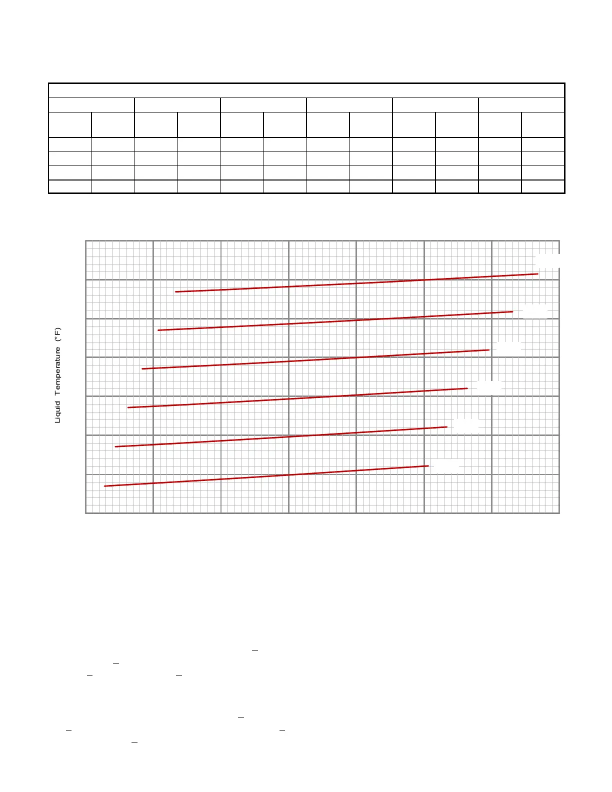
072 CHARGING CURVE - REHEAT - ALL-ALUMINUM COIL - 581111-01
Suction Pressure (psig)
70
80
90
100
110
120
105 115 125 135 145 155
Outdoor Temperature (°F)
165 175
105°
95°
115°
85°
75°
65°
60
130
C-Compressor Controls
See unit wiring diagram to determine which controls are
used on each unit. Optional controls are identified on
wiring diagrams by arrows at junction points.
1- High Pressure Switch (S4)
The compressor circuit is protected by a high
pressure switch which opens at 640 psig +
10 psig
(4413 kPa +
70 kPa) and automatically resets at 475
psig +
20 psig (3275kPa + 138 kPa).
2- Low Pressure Switch (S87)
The compressor circuit is protected by a loss of
charge switch. Switch opens at 40 psig +
5 psig (276
+
34 kPa) and automatically resets at 90 psig + 5
psig (621 kPa + 34 kPa).
3- Diagnostics Sensors (RT46, RT48)
Two thermistors are located on specific points in the
refrigeration circuit. The thermistors provide constant
temperature feedback to the Unit Controller to protect
the compressor. Thermistors take the place of the
freezestat and low ambient pressure switch.
4- Compressor Crankcase Heater (HR1)
Crankcase heater must be energized at all times to
prevent compressor damage due to refrigerant
migration. Energize crankcase heater 24 hours before
unit start-up by setting thermostat so that there is no
cooling demand (to prevent compressor from cycling)
and apply power to unit.
 Loading...