Page 35
Field-Installed Accessories
When field-installing the following accessories, refer to
the latest online installation instruction.
TABLE 12
Accessory
Instruction #
Economizer 507227-XX
Outdoor Air Damper 506340-XX
Electric Heat 507250-XX
Smoke Detector 506437-XX
Factory Unit Controller Settings
Use the mobile service app to adjust parameters; menu
paths are shown in each table. Refer to the Unit Controller
manual provided with each unit.
Tables 13 through 16 show blower factory settings.
Record any field-adjusted settings in the blank column.
Tables 17 and 18 show control options. When applicable,
record field-specific information on the label located
inside the compressor access panel.
When field installing optional kits and accessories, the
Unit Controller must be configured to identify the option
before it will function. Refer to figures 36 and 37 to
determine whether the Unit Controller configuration I.D.
must change. To configure the option, use RTU MENU >
SETUP > INSTALL menu path. Press NEXT until
CONFIGURATION ID 1 or 2 appears depending on the
option installed. Change the appropriate character in the
configuration I.D. For example, when an economizer is
installed using a single enthalpy sensor, change
configuration I.D. 1, the second character, to “S”.
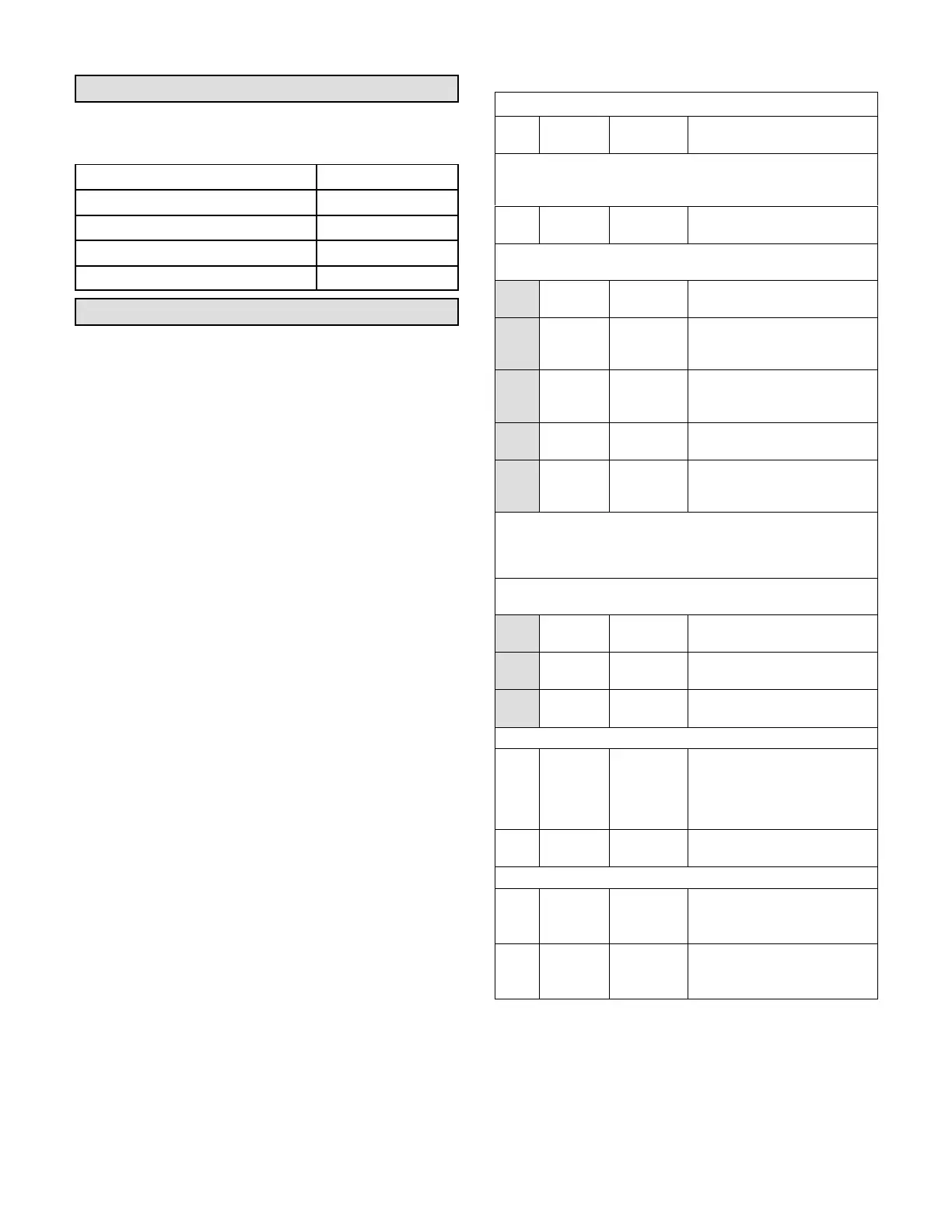
TABLE 13
LDT/LHT 092 (2-Compressor) Staged Direct Drive
Para
mete
r
Factory
Setting
Field
Setting
Description
Note: Any changes to Smoke CFM setting must be adjusted be
fore the other CFM settings. Use SETTINGS > RTU OPTIONS >
EDIT PARAMETERS
12
3000
CFM
CFM
Blower CFM during smoke
detection.
SETUP > TEST & BALANCE (can also use SETTINGS > RTU
OPTIONS > BLOWER > SPEEDS)
3000
CFM
CFM
Blower CFM during heating.
2625
CFM
CFM
Blower CFM during high speed
cooling (2 compressor)
operation.
800
CFM
CFM
Blower CFM during low speed
cooling (1 compressor)
operation.
800
CFM
CFM
Blower CFM during ventilation.
1195
RPM
RPM*
Adjust RPM based on unit static
and blower tables to reach tar
get CFM.
*Once all four blower settings are entered, the target (highest of the
heating and cooling settings) CFM will be displayed. Once the RPM
is saved for the target CFM, all other blower RPM values are set by
the Unit Controller according to the field CFM setting..
SETUP > TEST & BALANCE (can also use SETTINGS > RTU
OPTIONS > DAMPER)
0% %
Damper min. position during
LOW blower operation.
0% %
Damper min. position during
HIGH blower operation.
50% %
Min. Damper % for stage 1
power exhaust operation.
SETTINGS > RTU OPTIONS > EDIT PARAMETERS
29 101% %Open
Damper minimum position during
G blower operation. (Setting para
meter 29 to “101” disables para
meter 29 and passes control to
parameter 9 or 132)
216 10% %
Deadband % for stage 1 power
exhaust operation.
SETTINGS > RTU OPTIONS > EDIT PARAMETER
85 0°F °F
Compressor 1 low temp lockout.
Settings lower than 0°F could
void warranty.
86 0°F °F
Compressor 2 low temp lockout.
Settings lower than 0°F could
void warranty.
 Loading...