Page 31
I−UNIT COMPONENTS
CAUTION
Electrostatic discharge can affect electronic
components. Take precautions during furnace
installation and service to protect the furnace’s
electronic controls. Precautions will help to
avoid control exposure to electrostatic dis-
charge by putting the furnace, the control and the
technician at the same electrostatic potential.
Neutralize electrostatic charge by touching hand
and all tools on an unpainted unit surface, such
as the gas valve or blower deck, before perform-
ing any service procedure.
ELECTROSTATIC DISCHARGE (ESD)
Precautions and Procedures
LGA /LGC/LCA/LCC 21, 25 and 30 ton (74, 88 and 105 kW)
units are configure to order units (CTO). Unit components
are shown in figures 1 and 2. All units come standard with
hinged unit panels. The unit panels may be held open with
the door rod located inside the unit. All L1, L2, and L3 wiring
is color coded; L1 is red, L2 is yellow, and L3 is blue.
A−Control Box Components
Control box components are shown in figure 3, The control
box is located in the upper left portion of the compressor
compartment.
1−Disconnect Switch S48 (Optional all units)
All units may be equipped with an optional disconnect switch
S48. Other factory or field installed optional circuit breakers
may be used, such as CB10. S48 and CB10 are toggle
switches, which can be used by the service technician to dis-
connect power to the unit.
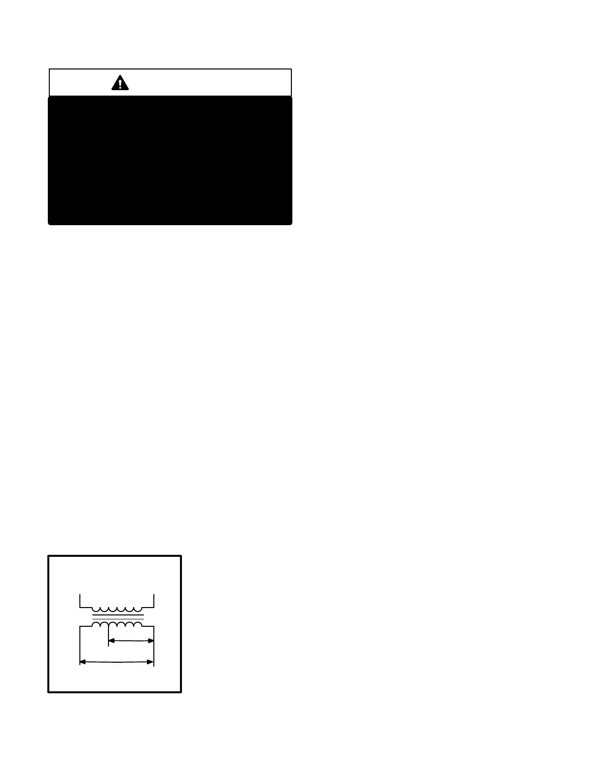
2−Control Transformer T1 (all units)
All units use a single line voltage to 24VAC transformer
mounted in the control box. Transformer supplies power
to control circuits in the unit. The transformer is rated at
70VA and is protected by a 3.5 amp circuit breaker
(CB8). The 208/230 (Y) voltage transformers use two
primary voltage taps
as shown in figure 4,
while 460 (G) and 575
(J) voltage transform-
ers use a single prima-
ry voltage tap. Units
will be factory wired for
230V (orange and
black). 208V (red and
black) applications
should be re−wired in
the field.
3−Contactor Transformer T18
T18 is a single line voltage to 24VAC transformer used in
all units. Transformer T18 is protected by a 3.5 amp circuit
breaker (CB18). T18 is identical to transformer T1. The
transformer supplies 24VAC power to the contactors.
4−C. A. B. Transformers T3 & T13
(460V & 575V units built prior to 10−2003)
LGA/LGC 460 (G) and 575 (J) voltage units built prior to
10−2003 use two auto voltage to 230VAC transformers
mounted in the control box. The transformers have an output
rating of 0.5A. T3 transformer supplies 230 VAC power to
combustion air inducer motor (B6), while T13 transformer sup-
plies power to combustion air inducer motor (B15).
5−Terminal Strips TB1, TB2, TB13, TB34, TB35
TB1 terminal strip distributes 24V power and common from
the thermostat to the control box components. TB13 termi-
nal strip distributes line voltage power to the line voltage
items in the unit. TB34 terminal strip distributes 24V pow-
er from T1 to the control box components. TB35 terminal
strip distributes 24V power from T18 to the contactors in
the control box. TB2 distributes line voltage to the unit
and is found more commonly on LCA/LCC units
equipped with electric heat. TB2 can be replaced with
Disconnect switch S48. All L1, L2, and L3 wiring is color
coded; L1 is red, L2 is yellow, and L3 is blue.
6−Outdoor Fan Motor Fuse Block & Fuses F10
(all units)
Three line voltage fuses F10 provide overcurrent protec-
tion to all condenser fans (and optional power exhaust
fans) in all units. The fuses are rated at 30A in 208/230V
units and 15A in all others.
7−Unit Fuse Block & Fuses F4
(LCA/LCC units only)
Three line voltage fuses F4 provide short circuit and ground
fault protection to all cooling components in the LCA/LCC
units. The fuses are rated in accordance with the amperage of
the cooling components.
8−Outdoor Fan Capacitors C1, C2, C18,
C19,C20, C21
Fan capacitors C1, C2, C18, C19, C20 and C21 are 370V /
10 MFD capacitors used to assist in the start up of condens-
er fans B4, B5, B21, B22, B23 and B24. respectively.
9−Compressor Contactors K1, K2, K14, K146
All compressor contactors are three pole double break
contactors with a 24VAC coil. In 3 compressor units
(early 360 model) K1 (energized by A55), K2 (energized
by A57), and K14 (energized by A59) energize compres-
sors B1, B2, and B13 respectively in response to first or
second stage cooling demands. In all other LGA/LGC/
LCALCC248H/360H units K1 (energized by A55), K2
(energized by A57), K14 and K146 (energized by A59)
energize compressors B1, B2, B13, and B20 respec-
tively.
FIGURE 4
BLUE YELLOW
ORANGE
RED
BLACK
230 VOLTS
208 VOLTS
PRIMARY
SECONDARY
208/230V TRANSFORMER
 Loading...