Page 16
LGH/LCH036, 048, 060, 072, 074
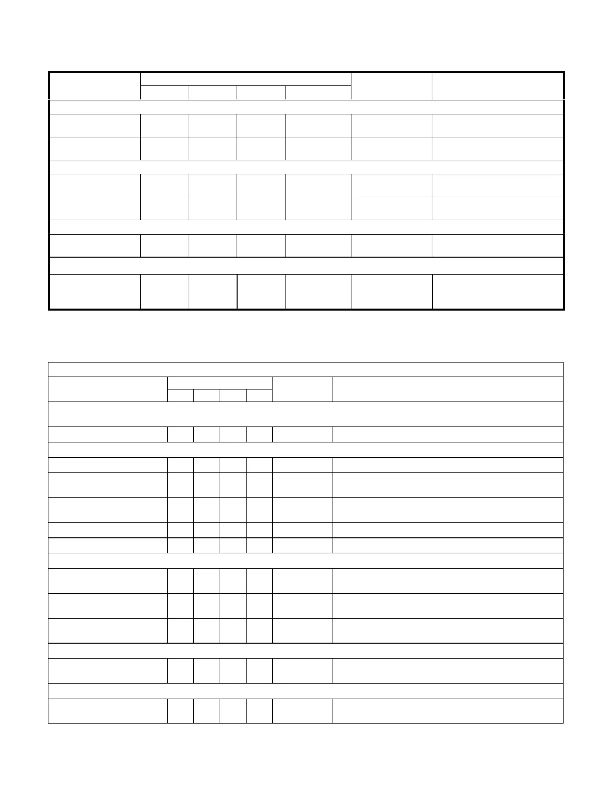
TABLE 6
036, 048, 060H DIRECT DRIVE PARAMETER SETTINGS
Parameter
LGH/LCH Unit Factory Default Settings
Field Setting Description
036 H4E 048 H4E 060 H4E 036-060 S4T
SETUP > TEST & BALANCE > BLOWER
HIGH SPEED 55% 58% 59% Not Applicable
Percentage torque for indoor
blower high speed.
LOW SPEED 28% 33% 36% Not Applicable
Percentage torque for indoor
blower low speed.
SETUP > TEST & BALANCE > DAMPER
BLOWER ON HIGH 0% 0 % 0 % 0 %
Minimum damper position during
high speed blower operation.
BLOWER ON LOW 0% 0% 0% Not Applicable
Minimum damper position during
low speed blower operation.
SETTINGS > RTU OPTIONS > EDIT PARAMETER = 6
BLOWER SMOKE
OUTPUT
55% 58% 59% Not Applicable
Percentage torque for indoor
blower smoke speed.
SETTINGS > RTU OPTIONS > EDIT PARAMETER = 10 (Applies to Thermostat Mode ONLY)
FREE COOLING
STAGE-UP DELAY
300 sec. 300 sec. 300 sec. 300 sec. sec
Number of seconds to hold indoor
blower at low speed before switch
ing to indoor blower at high speed.
Installer: Circle applicable unit model number and record any parameter changes under “Field Setting” column. Settings need to be recorded by
installer for use when Unit Controller is replaced or reprogrammed.
TABLE 7
036, 048, 060, 074U DIRECT DRIVE PARAMETER SETTINGS
LGH/LCH036-074U4E Parameter Settings
Parameter
Factory Setting
Field
Setting
Description
036 048 060 074
Note: Any changes to Smoke CFM setting must be adjusted before the other CFM settings. Use SETTINGS > RTU OPTIONS > EDIT
PARAMETERS = 12
BLOWER SMOKE CFM 1200 1600 2000 2400 CFM Smoke blower speed
SETUP > TEST & BALANCE > BLOWER
BLOWER HEATING HIGH CFM 1200 1600 2000 2000 CFM High heat blower speed
BLOWER HEATING LOW CFM N/A 1250 1250 1250 CFM
Low heat blower speed (applies to 150kBtuh 4-stg. gas heat
only)
BLOWER COOLING HIGH
CFM
1100 1450 1825 2200 CFM High cooling blower speed
BLOWER COOLING LOW CFM 575 750 950 950 CFM Low cooling blower speed
BLOWER VENTILATION CFM 575 750 950 1150 CFM Ventilation blower speed
SETUP > TEST & BALANCE > DAMPER
BLOWER HIGH CFM DAMPER
POS %
0% 0% 0% 0% % Minimum damper position for high speed blower operation.
BLOWER LOW CFM DAMPER
POS %
0% 0% 0% 0% % Minimum damper position for low speed blower operation.
POWER EXHAUST DAMPER
POS %
50% 50% 50% 50% % Minimum damper position for power exhaust operation.
SETTINGS > RTU OPTIONS > EDIT PARAMETERS = 216
POWER EXHAUST DEAD
BAND %
10% 10% 10% 10% % Deadband % for power exhaust operation.
SETTINGS > RTU OPTIONS > EDIT PARAMETER = 10 (Applies to Thermostat Mode ONLY)
FREE COOLING STAGE-UP
DELAY
300
sec.
300
sec.
300
sec.
300
sec.
sec
Number of seconds to hold indoor blower at low speed before
switching to indoor blower at high speed.
Installer: Circle applicable unit model number and record any parameter changes under “Field Setting” column. Settings need to be recorded
by installer for use when Unit Controller is replaced or reprogrammed.

 Loading...

