Page 63
LGH/LCH036, 048, 060, 072, 074
BEnter Supply Air CFM Into Unit Controller
Use the following menu path to enter each supply air CFM
into the Unit Controller. Make sure supply air CFM is
within limitations shown in table 37. Refer to the Unit
Controller manual provided with unit.
SETTING > RTU OPTIONS > BLOWER > SPEEDS
In the SPEEDS sub-menu, enter CFM values for HEAT,
COOLING HIGH, COOLING LOW and VENTILATION.
Use the down, up and save push buttons below the
display to enter each value.
After the speed CFM are saved, the Unit Controller will
cycle to BLOWER CALIBRATION.
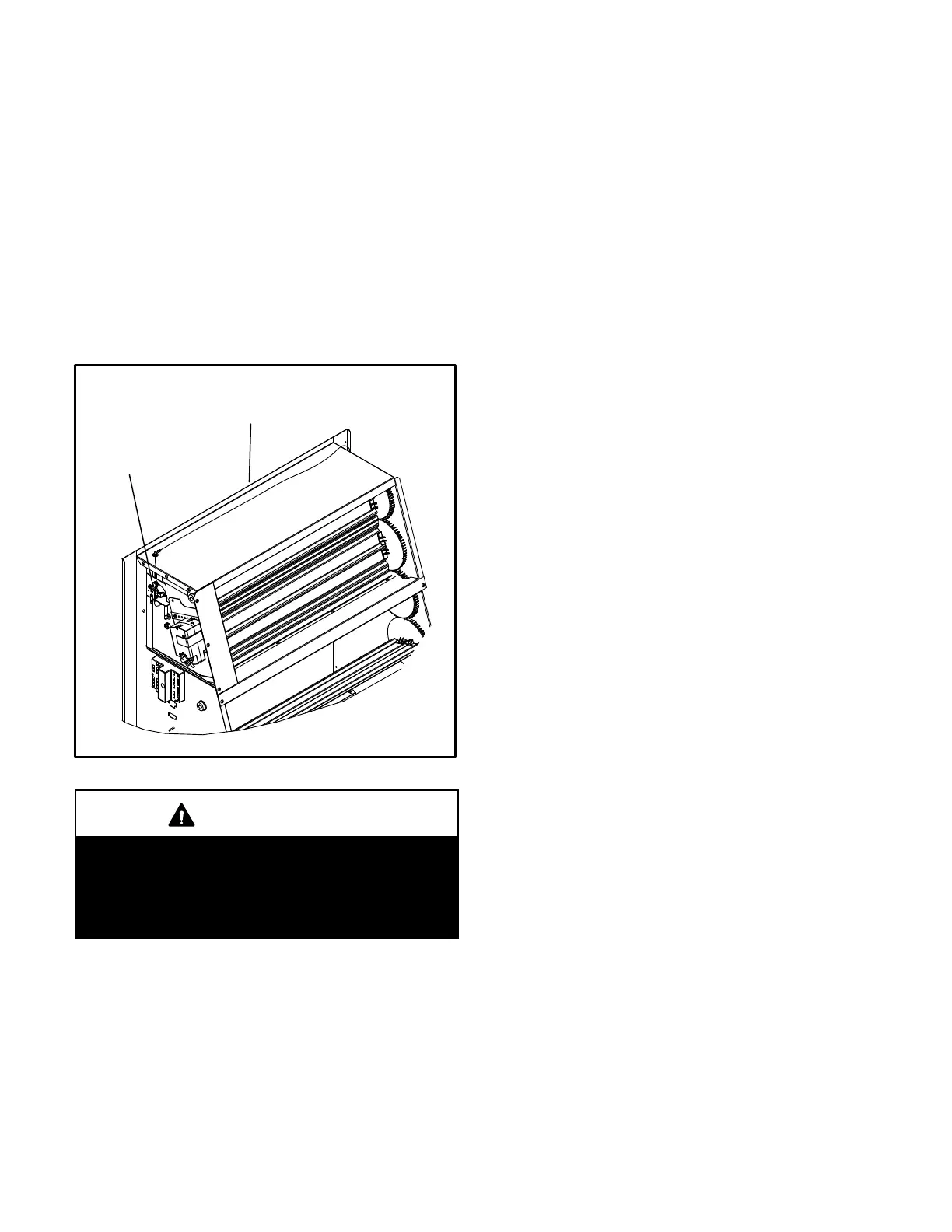
PT5 PRESSURE TRANSDUCER
PRESSURE
TRANSDUCER
FIGURE 27
ECONOMIZER
CAUTION
The BLOWER CALIBRATION process starts the in
door blower at operational speeds and moves the
economizer damper blades. Before starting this pro
cess, replace any access panels and close all unit
doors except compressor compartment door.
Blower calibration is required only on units that are newly
installed or if there is a change in the duct work or air filters
after installation. After the new CFM values are entered,
use the down and up arrow buttons to select START
CALIBRATION. Push SAVE to start calibration. The
blower calibration status is displayed as a % complete.
Upon successful completion, the Unit Controller will
display CALIBRATION SUCCESS and go back to the
blower calibration screen. Press the MAIN MENU button
to go to the main menu and press the BACK button to go
to the status screen.
If only the CFM values are updated, use the down and up
arrow buttons to select “CALIBRATION DONE”. Push
SAVE to enter the updated values. This selection will not
initiate calibration, resulting in less setup time. Press the
MAIN MENU button to go to the main menu and press the
BACK button to go to the status screen.
CEnter Outdoor Airflow Design Specifications Into
Unit Controller
Use the following menu path to enter the outdoor airflow
CFM (replaces minimum damper position set point) into
the Unit Controller. Make sure outdoor airflow CFM is
within limitations shown in table 37. Refer to the Unit
Controller manual provided with unit.
SETTINGS > RTU OPTIONS > DAMPER
Press the SAVE button to cycle through the sub-menu
until the OUTDOOR AIRFLOW input screen is displayed.
Enter the value and press SAVE.
Press the MAIN MENU button to go to the main menu and
press the BACK button to go to the status screen.
DOperation
1- After calibration, the indoor blower will supply the
CFM specified based on the thermostat demand
signal received by the Unit Controller:
G – Ventilation CFM
W – Heating CFM
Y1 – Cooling Low CFM
Y2 – Cooling High CFM
2- The Unit Controller, using input from PT5 and the
entered outdoor air flow CFM, will open the fresh
air dampers to minimum position. In addition, the
Unit Controller must have an occupied (OCP)
thermostat demand.

 Loading...

