Page 28
TABLE 7
GAS VALVE REGULATION FOR LGT UNITS
Max Inlet
Pressure
“W.C.
Operating Pressure “W.C.
(outlet) Factory Setting
Natural L.P. Propane
Low Low
1.6+ + + +
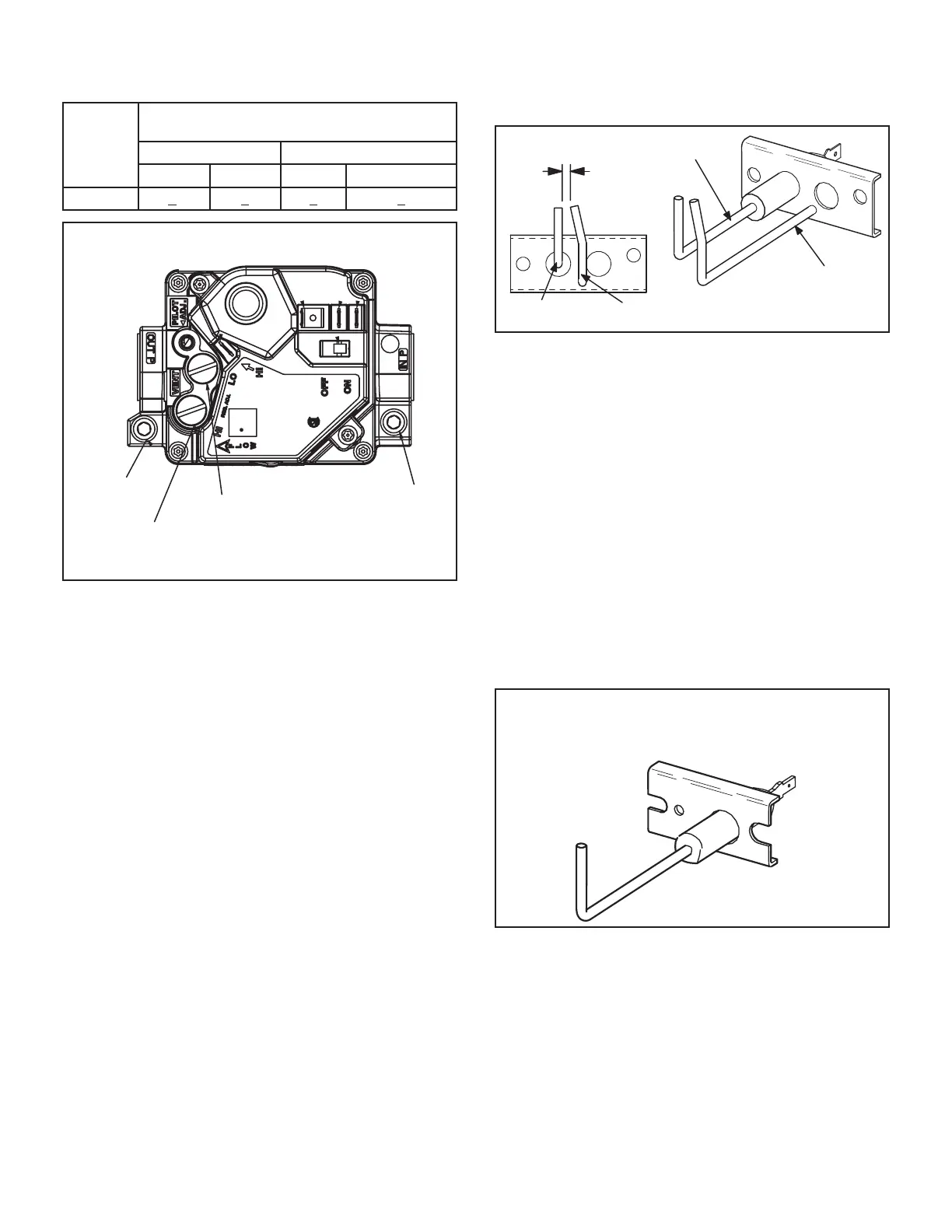
WHITE RODGERS 36H54 GAS VALVE
Two-Stage
GAS VALVE SWITCH SHOWN IN ON POSITION.
Inlet Pressure Tap
Outlet Pressure
Tap
High Fire Adjustment
(under cap)
Low Fire Adjustment
(under cap)
FIGURE 20
11-Spark Electrodes
An electrode assembly is used for ignition spark. Two iden-
tical electrodes are used (one for each gas heat section).
The electrode is mounted through holes on the left-most
end of the burner support. The electrode tip protrudes into
assembly is fastened to burner supports and can be re-
moved for service without removing any part of the burn-
ers.
burner to burner until all are lit.
The spark electrode is connected to the ignition control
by a 8 mm silicone-insulated stranded high voltage wire.
electrode end and female spark plug-type terminal on the
ignition control end
NOTE-IN ORDER TO MAXIMIZE SPARK ENERGY TO
ELECTRODE, HIGH VOLTAGE WIRE SHOULD
TOUCH UNIT CABINET AS LITTLE AS POSSIBLE.
GROUND
ELECTRODE
GROUND
ELECTRODE
.125” ± .015”
(3.2 mm ± .4 mm)
FIGURE 21
12-Flame Sensors
-
er support. The sensor is mounted through a hole in the
-
lope of the right most burner. The sensor assembly is fas-
tened to burner supports and can be removed for service
without removing any part of the burners.
-
diately.
-
tion control allows the gas valve to stay open as long as a
FIGURE 22
 Loading...

