Page 14
I-UNIT COMPONENTS
WARNING
Electric shock hazard. Can cause injury
or death. Before attempting to perform
any service or maintenance, turn the
electrical power to unit OFF at discon
nect switch(es). Unit may have multiple
power supplies.
All 7.5 through 12.5 ton (38.1 through 70.3 kW) units are
configure to order units (CTO). The LGT unit components
are shown in figure 1. All units come standard with hinged
unit panels. All L1, L2 and L3 wiring is color coded; L1 is red,
L2 is yellow and L3 is blue.
A-Control Box Components
ELECTROSTATIC DISCHARGE (ESD)
Precautions and Procedures
CAUTION
Electrostatic discharge can affect elec
tronic components. Take precautions to
neutralize electrostatic charge by
touching your hand and tools to metal
prior to handling the control.
LGT control box components are shown in figure 2. The
control box is located in the upper portion of the compressor
compartment.
1-Disconnect Switch S48 (Optional)
All units may be equipped with an optional disconnect
switch S48. Other factory or field installed optional circuit
breakers may be used, such as CB10. S48 and CB10 are
toggle switches, which can be used by the service techni
cian to disconnect power to the unit.
2-Control Transformer T43 (Re-Heat Units)
T43 is a single line voltage to 24VAC and ties into T1. See
unit diagram. T43 is mounted in the control box. The trans
former supplies power to control circuits (through T1).The
transformer is rated at 70VA and is protected by a 3.5 amp
circuit breaker (CB8). The 208/230 (Y) voltage transform
ers use primary voltage taps as shown in figure 3, while 460
(G) and 575 (J) voltage transformers use a single primary
voltage tap.
3-Control Transformer T1
All use a single line voltage to 24VAC transformer mounted
in the control box. Transformer supplies power to control
circuits in the unit. The transformer is rated at 92VA and is
protected by a 6 amp circuit breaker (CB8). The 208/230
(Y) voltage transformers use primary voltage taps as
shown in figure 3, while 460 (G) and 575 (J) voltage trans
formers use a single primary voltage tap.
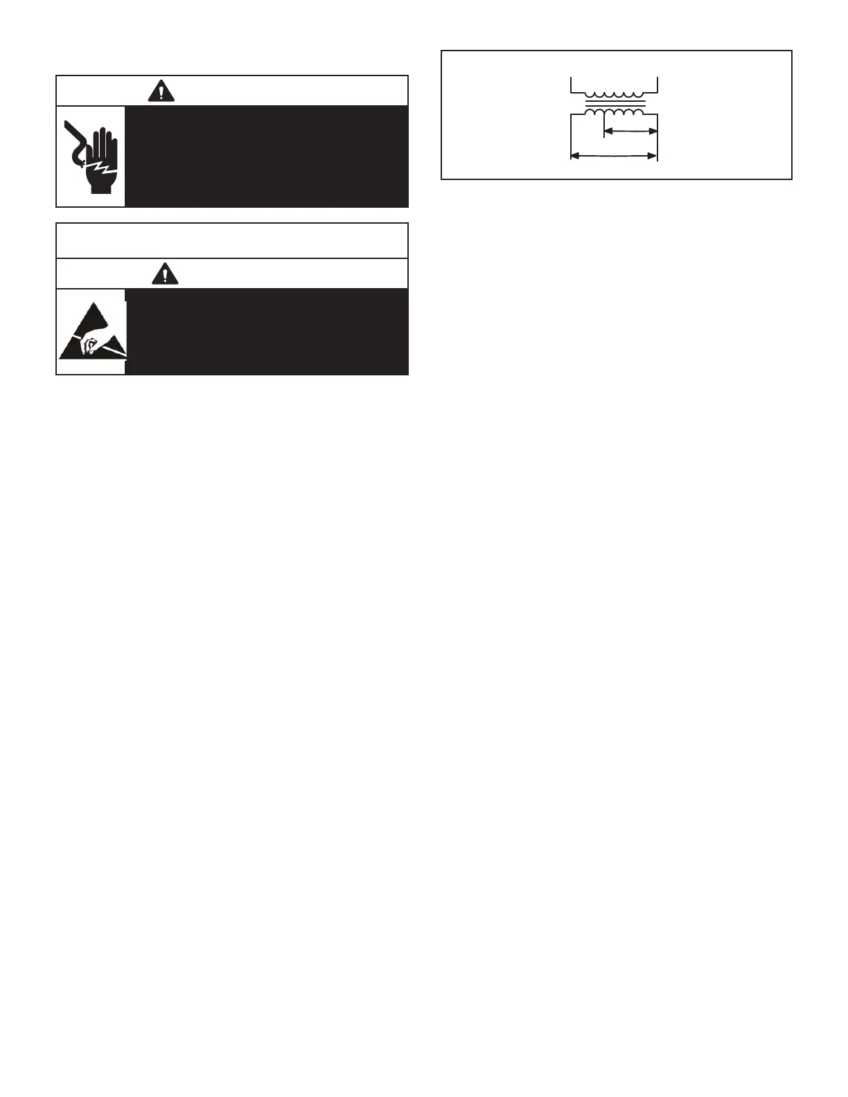
FIGURE 3
BLUE YELLOW
ORANGE
RED
BLACK
230 VOLTS
208 VOLTS
PRIMARY
SECONDARY
208/230V TRANSFORMER
4-Outdoor Fan Relay K10, K68
Outdoor fan relays K10 and K68 are DPDT relays with a
24VAC coil. In standard and high efficiency units, K10 and
K68 energize condenser fans B4 and B5.
5-Outdoor Fan Capacitors C1, C2
Fan capacitors C1 and C2 are used to assist in the start up
of condenser fans B4 and B5. Capacitor size varies with
unit tonnage and voltage.
LGT092-102 all voltages - 370V/10 MFD
LGT120-150 J volt - 370/10 MFD
LGT120-150 G volt - 370V/12.5 MFD
LGT120-150 Y volt - 370V/15 MFD
6-C. A. I. Transformers T3 575V Units
All LGT 575 (J) voltage units use transformer T3. The auto
voltage to 230VAC transformer is mounted in the control
box. The transformer has an output rating of 0.5A. T3 trans
former supplies 230 VAC power to combustion air blower
motor (B6).
7-Compressor Contactor K1, K2
All compressor contactors are three‐pole, double‐break
contactors with 24VAC coils. K1 and K2 (both energized by
A55) energize compressors B1 and B2.
8-Burner Controls A3
A3 controls gas heat section burner controls. Burner con
trols are factory set and are not adjustable. The control
makes three attempts at ignition and then locks out the sys
tem if ignition is not obtained after the third trial. Reset after
lockout requires only breaking and remaking thermostat
demand. The control shuts off gas flow immediately in the
event of a gas or power failure. Upon restoration of gas and
power, the control will restart the ignition sequence and
continue until flame is established or system locks out. For
a more detailed description see the Gas Heat Components
section.
9-Power Exhaust Relay K65 (PED units)
Power exhaust relay K65 is a N.O. DPDT relay with a
24VAC coil. K65 is used in all LGT units equipped with the
optional power exhaust dampers. K65 is energized by the
economizer control panel (A56), after the economizer
dampers reach 50% open (adjustable in CORE). When
K65 closes, the exhaust fan B10 is are energized.
 Loading...


