Page 6
LGT/LCT156, 180, 210, 240, 300
Shipping and Packing List
Package 1 of 1 contains:
1- Assembled unit
Check unit for shipping damage. Receiving party should
contact last carrier immediately if shipping damage is found.
General
These instructions are intended as a general guide and
do not supersede local codes in any way. Authorities
having jurisdiction should be consulted before
installation.
The LGT156H gas/electric packaged rooftop unit is
available in 169, 000, 260,000, & 360,000 Btuh heating
input. The LGT180, 210, 240, & 300 gas/electric
packaged rooftop units are available in 260,000,
360,000, or 480,000 Btuh heating inputs.
The LCT cooling packaged rooftop unit is the same basic
design as the LGT unit except for the heating section.
Optional electric heat is factory- or field-installed in LCT
units.
LGT and LCT units have identical refrigerant circuits with
respective 13, 15, 17‐1/2, 20 and 25 ton cooling
capacities. 156H units contain two compressors;
compressor 1 is two speed and compressor 2 is fixed
speed. 180H units contain three compressors; all are
fixed speed. 210, 240 and 300 units contain four
compressors; all are fixed speed compressors.
Units come standard with a factory-installed, all-aluminum
condenser coil.
Units are available with an optional hot gas reheat coil
which provides a dehumidifying mode of operation. Refer
to Reheat Operation section.
Units are available with variable air volume or single-zone
variable air volume. Refer to the 9
th
character of the
model number to determine type of blower:
V - Variable Air Volume
M - Single-Zone Variable Air Volume
Units use R410A, an ozone-friendly HFC refrigerant.
Refer to the Cooling Start-Up section for precautions
when installing unit.
WARNING
Electric shock hazard and danger of
explosion. Can cause injury, death or
product or property damage. Turn off
gas and electrical power to unit before
performing any maintenance or
servicing operations on the unit. Follow
lighting instructions attached to unit
when putting unit back into operation
and after service or maintenance.
Requirements
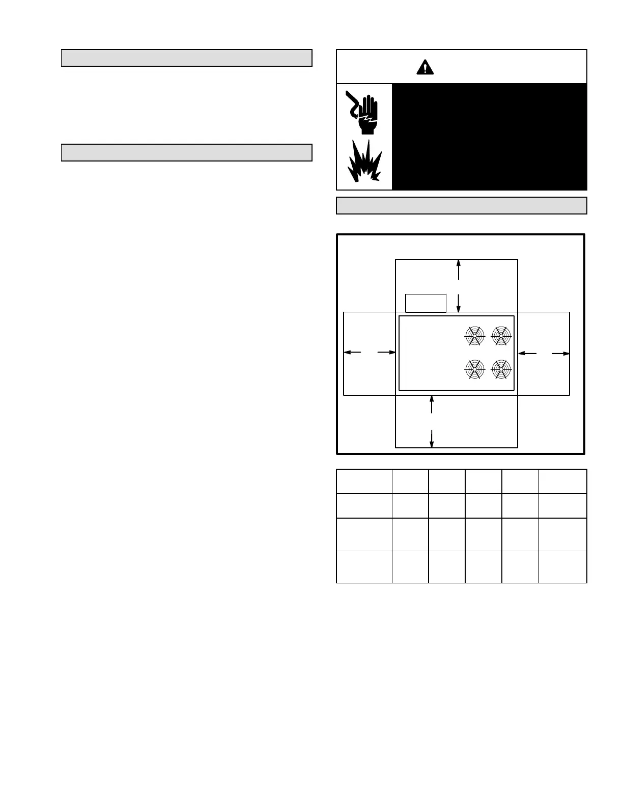
See figure 1 for unit clearances.
UNIT CLEARANCES
C
D
B
A
FIGURE 1
Optional
Outdoor
Air Hood
1
Unit
Clearance
A
in.(mm)
B
in.(mm)
C
in.(mm)
D
in.(mm)
Top
Clearance
Service
Clearance
60
(1524)
36
(914)
36
(914)
66
(1676)
Unob
structed
Clearance to
Combus
tibles
36
(914)
1 (25) 1 (25) 1 (25)
Unob
structed
Minimum
Operation
Clearance
36
(914)
36
(914)
36
(914)
41
(1041)
Unob
structed
Note - Entire perimeter of unit base requires support when elevated above
mounting surface.
1
Service Clearance - Required for removal of serviceable parts.
Clearance to Combustibles - Required clearance to combustible material
(gas units). On LCT units, see clearance to combustible materials outlined
on heater rating plate.
Minimum Operation Clearance - Required clearance for proper unit operation.
 Loading...