Page 77
508288-01 9/2022
Service
The unit should be inspected once a year by a qualified
service technician.
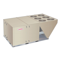
A-Filters
Units are equipped with six 24 X 24 X 2” filters. Filters
should be checked monthly and replaced when
necessary with filters of like kind and size. Take note of
air flow direction marking on filter frame when
reinstalling filters. See figure 39.
NOTE-Filters must be U.L.C. certified or equivalent for
use in Canada.
FIGURE 39
REMOVE FILTERS
PULL TO
REMOVE
FILTERS
CAUTION
Label all wires prior to disconnection when servic
ing controls. Wiring errors can cause improper and
dangerous operation. Verify proper operation after
servicing.
B-Lubrication
All motors are lubricated at the factory. No further
lubrication is required.
Blower shaft bearings are prelubricated. For extended
bearing life, relubricate at least once every two years with
a lithium base grease, such as Alvania 3 (Shell Oil),
Chevron BRB2 (Standard Oil) or Regal AFB2 (Texas Oil).
Use a hand grease gun for relubrication. Add only enough
grease to purge through the bearings so that a bead of
grease appears at the seal lip contacts.
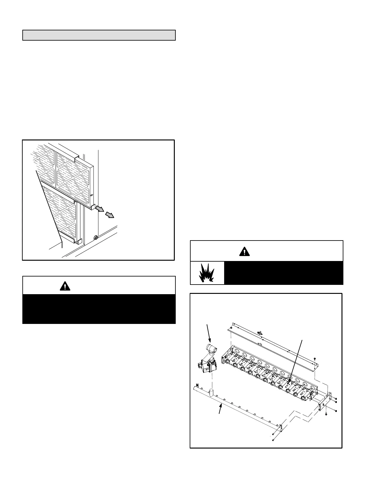
C-Burners (Gas Units)
Periodically examine burner flames for proper
appearance during the heating season. Before each
heating season examine the burners for any deposits or
blockage which may have occurred.
Clean burners as follows:
1- Turn off both electrical power and gas supply to unit.
2- Open burner compartment access panel.
3- Remove screws securing burner assembly to burner
support and remove assembly. See figure 40. Clean
as necessary.
4- Locate the ignitor under the left burners. Check
ignitor spark gap with appropriately sized twist drills
or feeler gauges. See figure 41.
5- Check the alignment of the ignitor and the sensor as
shown in figure 42 and table 21.
6- Replace burners and screws securing burner.
7- Replace access panel.
8- Restore electrical power and gas supply. Follow
lighting instructions attached to unit and use
inspection port in access panel to check flame.
WARNING
Danger of explosion. Can cause injury or
death. Do not overtighten main burner
mounting screws. Snug tighten only.
BURNER BOX ASSEMBLY
480BTUH SHOWN
FIGURE 40
GAS
MANIFOLD
GAS
VALVE
BURNER ASSEMBLY
SECURED WITH
MULTIPLE SCREWS
 Loading...