14
Technical Information
Service Manual
4. Refrigerant System Diagram
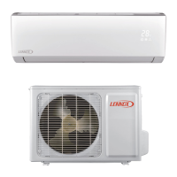
Indoor unit
Outdoor unit
Accumlator
Discharge
Suction
Heat
exchanger
(evaporator)
Heat
exchanger
(condenser)
Valve
Valve
Liquid pipe
side
Gas pipe
side
Strainer
Capillary
Compressor
Electron
expansion
valve
Connection pipe specication:
Liquid pipe:1/4"
Gas pipe:5/8" LI024CI-210P432,LI024CO-210P432
Gas pipe:1/2" LI018CI-210P432,LI018CO-210P432
Gas pipe:3/8" LI012CI-210P432,LI012CO-210P432
 Loading...