Page 29
DEFROST CONTROL CMC1
NOTE - For geographic areas that experience low tem-
perature and high humidity conditions (below 32°F and
above 80% RH), the defrost timer pin must be eld set at
installation to a 60 or 30 minute defrost interval in order to
ensure reliable system operation while in heating mode.
LRP14HP and LRP16HP units are equipped with a defrost
control that includes the combined functions of time/ tem-
perature defrost control, defrost relay, diagnostic LEDs
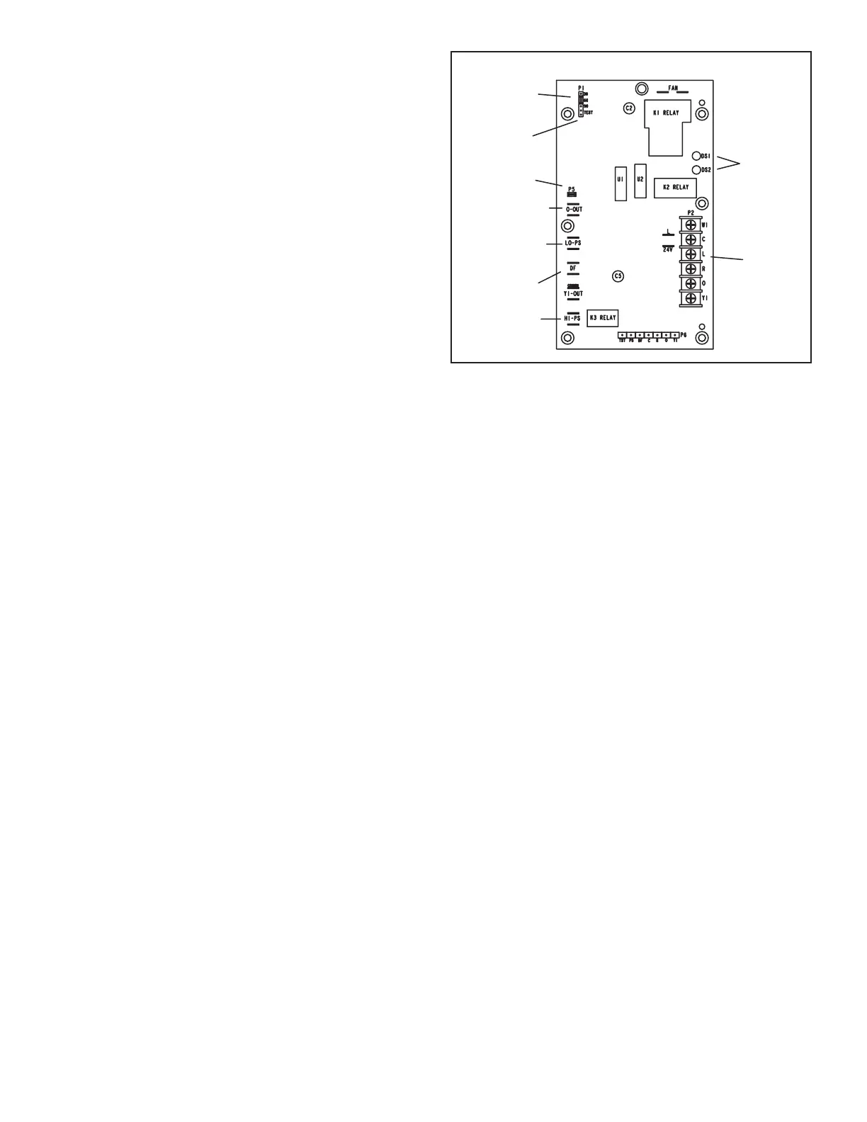
and a low voltage terminal strip. See gure 10.
The control provides automatic switching from call for
heating to defrost mode and back. During the compressor
cycle (call for defrost), the control accumulates compres-
sor run time at 30, 60 or 90-minute eld-adjustable inter-
vals. If the defrost thermostat is closed when the selected
compressor run time interval ends, the defrost relay is en-
ergized and the defrost begins.
The defrost timing is factory set to provide a 30-minute de-
frost interval. If the timing selector jumper is not in place,
the control defaults to a 90-minute defrost interval. The
maximum defrost period is 14 minutes and is not adjust-
able. See gure 10 for the location of the defrost interval
timing pins.
A test option is provided for troubleshooting. The test
mode may be started any time the unit is in the heating
mode and the defrost thermostat is closed or jumpered. If
the jumper is in the TEST position at power up, the control
will ignore the test pins. When the jumper is placed across
the TEST pins for 2 seconds, the control will enter the de-
frost mode. If the jumper is removed before an additional
5-second period has elapsed (7 seconds total), the unit will
remain in defrost mode until the defrost thermostat opens
or 14 minutes have passed. If the jumper is not removed
until after the additional 5-second period has elapsed, the
defrost will terminate and the test option will not function
again until the jumper is removed and reapplied.
NOTE - On early defrost controls, the defrost timing jump-
er must be in the 90-minute defrost interval before testing
the defrost mode or the control will not enter defrost test
mode.
The defrost control includes a compressor delay function
which cycles the compressor o for 30 seconds while go-
ing into and coming out of the defrost cycle. This function
is activated when the jumper is removed from the com-
pressor delay pins.
NOTE - The 30-second compressor delay is not functional
when the TEST pins are jumpered.
Defrost Control
Defrost Interval
Timing Pins
Test Pins
Compressor
Delay Pins
Reversing Valve
Low Pressure/
Loss of Charge
Switch
High Pressure
Switch
Defrost
Thermostat
Diagnostic
LEDs
24V Terminal
Strip
Connections
FIGURE 10
The defrost thermostat (S6) is located on the outdoor coil,
near the bottom of the coil, axed to the ⅜" stub. When
the defrost thermostat senses a coil temperature of 42°F
or cooler, the thermostat contacts close and send a sig-
nal to the defrost control to begin the defrost timing. The
defrost thermostat also terminates the defrost when the
coil distributor tube temperature warms to 70°F. The de-
frost control includes HI-PS and LO-PS terminals to re-
ceive signals from the unit high pressure switch and loss
of charge switch.
During a single demand cycle, the defrost control locks
out compressor operation after the fth time that the circuit
is interrupted by any pressure switch wired to the con-
trol. In addition, the diagnostic LEDs indicate a locked-out
pressure switch after the fth open pressure switch oc-
currence. Compressor operation remains locked out until
power to the control is interrupted, then re-established, or
until the jumper is applied to the TEST pins for 0.5 sec-
onds.
NOTE - The defrost control ignores input from the loss of
charge switch terminals as follows:
During the test mode;
During the defrost cycle;
During the 90-second start-up period;
During the rst 90 seconds following a reversing valve
switch between the heating and cooling modes.
EXCEPTION – If the TEST pins are jumpered and the
5-minute delay is being bypassed, the LO-PS terminal
signal is not ignored during the 90-second start-up
period.
The defrost control includes two diagnostic LEDs.
LED codes indicate operating status. The diagnostics
codes are given in table 3.