Page 30
TABLE 3
Defrost Control Diagnostic LEDs
Mode
Green LED
(DS2)
Red LED
(DS1)
No Power to
Control
OFF OFF
Normal Operation /
Power to Control
Simultaneous Slow Flash
Anti-Short Cycle
Lockout
Alternating Slow Flash
Low Pressure
Switch Fault
OFF Slow Flash
Low Pressure
Switch Lockout
OFF ON
High Pressure
Switch Fault
Slow Flash OFF
High Pressure
Switch Lockout
ON OFF
BLOWER COMPARTMENT
Access panels can easily be removed for service.
Blower Wheel
Blower wheel size varies between models. See SPECIFI-
CATIONS.
WARNING
Disconnect power from unit and wait at least
ve minutes to allow capacitors to discharge
before attempting to adjust motor speed tap
settings. Failure to wait may cause personal
injury or death.
REFRIGERATION COMPONENTS
Compressor B1 – LRP14 Units
LRP14GE/GN and LRP14AC (-024 and -030 models) uti-
lize a rotary compressor. All other LRP14 models utilize a
scroll compressor. Compressors are energized by the K1
contactor found in the unit control box. Compressor spec-
ications are found in the “ELECTRICAL DATA” section in
this manual.
Compressor B1 – LRP16GE/HP Units
All LRP16GE units utilize a two-stage Copeland scroll
compressor. Compressors are energized by the K1 con-
tactor found in the unit control box. Compressor speci-
cations are found in the “ELECTRICAL DATA” section in
this manual.
WARNING
Electrical shock hazard. Compressor must be grounded.
Do not operate without protective cover over terminals.
Disconnect power before removing protective cover.
Discharge capacitors before servicing unit. Failure to
follow these precautions could cause electrical shock
resulting in injury or death.
Condenser Fan B4 / Fan Motor B3 – LRP14 Units
LRP14 series units are equipped with a constant torque
blower motor. The constant torque motor is capable of
maintaining a specied CFM throughout the external
static range. Indoor fans are equipped with a permanent
magnet constant torque motor. These motors remain en-
ergized and are controlled by 24V signals. For high static
applications, use Tap 3 for cooling speed and Tap 5 for
heating speed.
All LRP14 series units use single phase condenser fan
motors. Specications for the condenser fans are at the
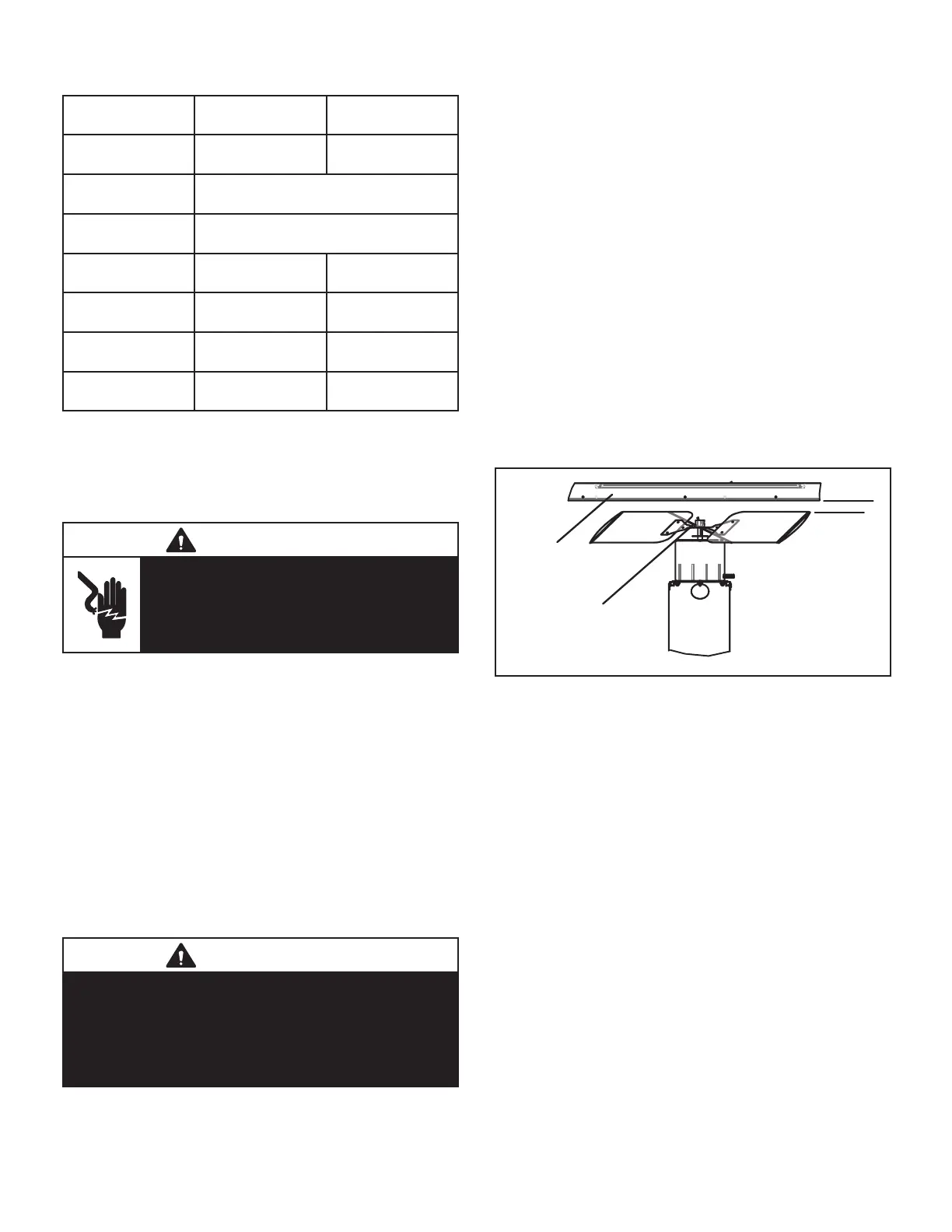
front of this manual. See gure 11 for fan and motor re-
placement dimensions.
Condenser Fan B4 / Fan Motor B3 – LRP16GE/HP Units
LRP16GE/HP units are equipped with a variable-speed di-
rect-drive blower operated by a variable-speed ECM mo-
tor. The ECM motor maintains a specied air volume from
0 through 0.80 in. w.g. static range.
All LRP16GE/HP units use single phase condenser fan
motors. Specications for the condenser fans are at the
front of this manual. See gure 11 for fan and motor re-
placement dimensions.
HUB AND
SHAFT SHOULD
BE FLUSH
FAN GUARD
1 1/2”
FIGURE 11
Reversing Valve L1
Reversing valve L1 has a 24 volt solenoid coil which re-
verses refrigerant flow during unit operation in all
LRP14HP and LRP16HP units. The reversing valve is in
the refrigerant circuit vapor line. The reversing valve coil
is energized during cooling demand and during defrost.
Low Pressure Switch S79 (LRP14GE, AC, LRP16GE
Units)
S79 is a N.C. auto-reset low pressure switch located on
the suction line. The switch shuts o the compressor when
suction pressure falls below the factory setting. The switch
is ignored during the rst 90 seconds of compressor start
up and during defrost operation. On the LRP14/16 series
units, the switch is set to open at 25 ± 5 psi and close at
40 ± 5 psi. S79 is not adjustable.
Loss of Charge Pressure Switch S79 (LRP14HP-02 –
LRP16HP Units)
The low pressure switch is an auto-reset N.C. switch that
opens on pressure drop. The switch is wired into the de-
frost board low pressure terminals and is located on the
liquid (high pressure) line . When suction pressure drops
to 40 psig (275.8 kPa) the switch opens and the compres-
sor is de-energized. When suction pressure rises to 90
psig (620.5 kPa) the pressure switch will close.