Page 33
5 - Test capacitor. Replace as necessary.
6 - Inspect contactor contacts for pitting or burn marks.
Replace as necessary.
7 - Check fan motor for worn bearings/bushings.
Replace as necessary.
8 - Inspect and clean coils, if necessary and note any
damage to coils or signs of leakage.
Filters
1 - Internal lter kits containing lter rails for 1 in. thick
lters are available. Filters are not provided and
must be eld supplied. A lter is required, whether
installed in the unit, in the ductwork or behind a lter
grill in the conditioned area.
NOTE - If PCO is installed, an internal lter kit is not rec-
ommended.
2 - Filters should be inspected monthly. Replace
disposable lters or clean permanent-type lters as
necessary. Dirty lters are the most common cause
of inadequate heating or cooling performance.
Replace existing lter with a lter of like type and
size. DO NOT replace a permanent-type lter with
a disposable lter. Install new/clean lters with the
arrows on the side pointing in the direction of airow.
Healthy Climate® Photocatalytic Oxidation (PCO) Air
Purication Accessory (LRP16 Series Only)
1 - The Healthy Climate® PCO cartridge and UVA
lamp require annual replacement. An annual
maintenance kit is available that includes the PCO
cartridge and UVA lamp. More frequent replacement
may be required in applications with heavier dust or
dirt loads or in applications where a lower MERV
lter is installed before the Healthy Climate® PCO
cartridge. The eld supplied lter should be changed
at least annually, or according to the manufacturers
recommended replacement cycle.
General System Test with System Operating
1 - Perform a general system test. Turn on the air
conditioner to check operating functions such as
the startup and shuto operation. Check for unusual
noises or odors, and measure indoor/outdoor
temperatures and system pressures as needed.
Check the refrigerant charge per the charging
sticker information on the unit.
2 - Refer to the nameplate to determine the correct
temperature rise for all gas units (GE / DF).
3 - Verify that system total static pressure and airow
settings are within specic operating parameters.
4 - Verify correct temperature drop across indoor coil.
POST START-UP CHECKLIST (GAS)
After the control circuit has been energized and the heat-
ing section is operating, make the following checks:
1 - Use soap solution to check for gas leaks in the unit
piping as well as the supply piping.
2 - Check the supply gas pressure. It must be within the
limits shown on rating nameplate. Supply pressure
should be checked with all gas appliances in the
building at full re. At no time should the supply gas
pressure exceed 10.5 inches w.c., nor drop below
5.0 inches w.c. for natural gas units. For propane
gas, supply gas pressure should not drop below 11
inches w.c. If gas pressure is outside these limits,
contact your gas supplier for corrective action.
3 - Check for correct manifold gas pressures. See
Check and Adjust Manifold Pressure.
4 - Adjust temperature rise to the range specied on
the rating plate.
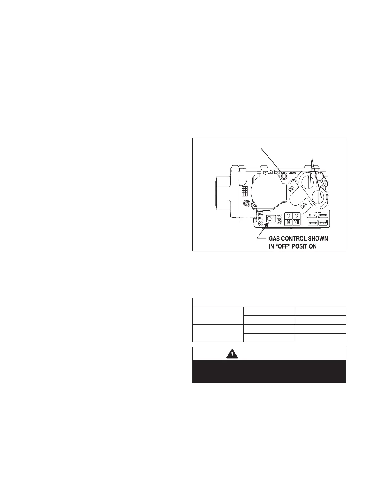
Check and Adjust Manifold Pressure
After line pressure has been checked and adjusted, check
manifold pressure. Refer to gure 14 for location of man-
ifold pressure adjustment screw and pressure tap outlet.
MANIFOLD PRESSURE
TEST TAP
REGULATOR
ADJUSTMENT
(UNDER CAP)
FIGURE 14
The gas valve is factory set and should not require adjust-
ment. See the table below for pressures. The gas valve
should completely and immediately cycle o in the event
of gas or power failure. The manual shut-o knob or switch
can be used to immediately shut o gas supply.
Manifold Pressure " w.c.
1st Stage Heat
Natural 2.0 ± 0.3
LP 5.6 ± 0.3
2nd Stage Heat
Natural 3.5 ± 0.3
LP 10.0 ± 0.5
IMPORTANT
For safety, connect a shut-o valve between the
manometer and the gas tap to permit shut o of gas
pressure to the manometer.
1 - Connect a test gauge to the outlet pressure tap on
the gas valve. Start the unit and allow ve minutes
for the unit to reach steady state.
2 - While waiting for the unit to stabilize, notice the
ame. The ame should be stable without ashback
and should not lift from the burner head. Natural
gas should burn blue. L.P. gas should burn mostly
blue with some orange streaks.
 Loading...
