Installation - Operation - Maintenance manual (IOM) • AIR COOLED CHILLERS & SPLIT UNITS - 1106-E • 48 •
ECOLOGIC - hydraulic/hydronic data
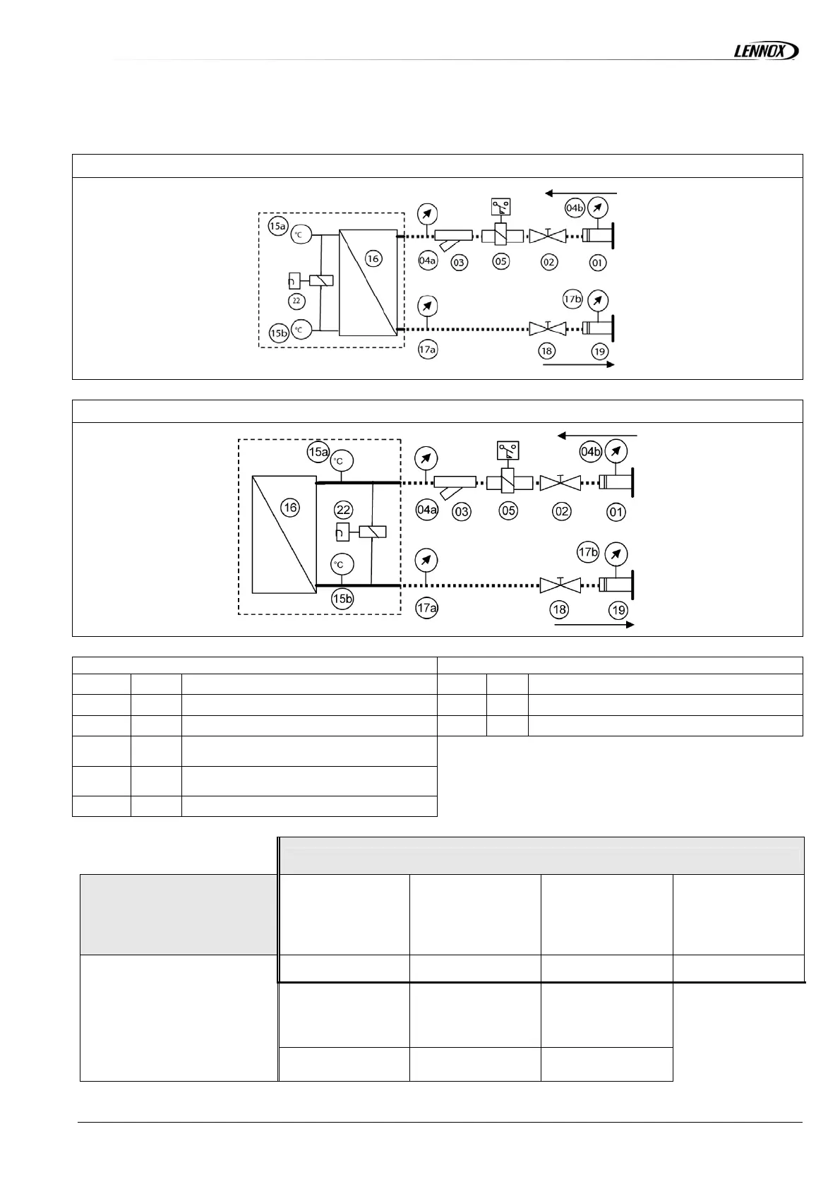
UNIT WITHOUT HYDRAULIC OR HYDRONIC MODULE
WA 150 STD – LN / WA 75 – 100 – 110 HE – SLN
WA 270 Æ 370 STD – LN – HE – SLN / WA 90 – 130 - 150 HE – SLN
ITEMS SUPPLIED LOOSE ITEMS MOUNTED INSIDE THE UNIT
01 19
Groove lock coupling
15a 15b
Temperature sensors
02 18
Unit isolation valve
16
Plate heat exchanger
03
Water inlet filter
22
Flow switch/Differential
04a 17a
In/Out manometers without groove lock
coupling option
04b 17b
in/Out manometers mounted on groove
lock coupling option
05
Paddle flow switch
OPTIONS
BASIC UNIT
Water inlet filter
Flow switch (paddle)
Supplied loose
Flow switch (differential)
Supplied mounted
Unit isolation valve
Add 03
Add 05
Add 22
Add 02/18
Kit for groove lock coupling Inlet/Outlet manometer
Inlet/Outlet manometer +
kit for groove lock coupling
16
15a/15b
Add 01/19
Add 04a/17a
Add 04b/17b & 01/19
 Loading...