Installation - Operation - Maintenance manual (IOM) • AIR COOLED CHILLERS & SPLIT UNITS - 1106-E • 49 •
ECOLOGIC - hydraulic/hydronic data
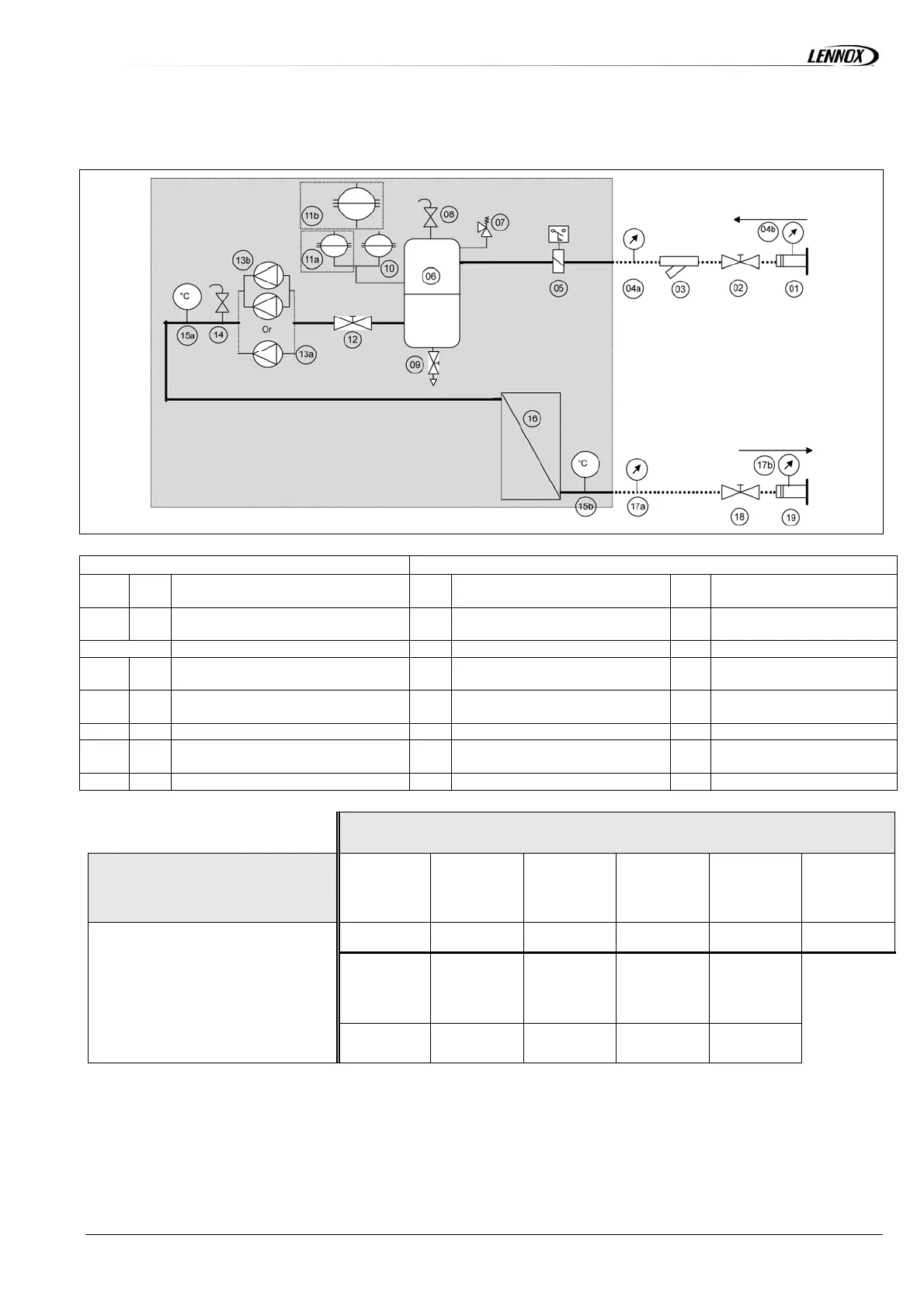
UNIT WITH HYDRONIC MODULE
ITEMS SUPPLIED LOOSE ITEMS MOUNTED INSIDE THE UNIT
01 19
Groove lock coupling
05
Paddle flow switch
11b
Single 50L expansion
vessel (WA <= 150D)
02 18
Unit isolation valve
06
Water tank 200L or 500L
12
Pump suction isolation
valve
03
Water inlet filter
07
Safety valve
13a
Single pump
04a 17a
In/Out manometers without groove
lock coupling option
08
Air purge
13b
Double pump
04b 17b
In/Out manometers mounted on
groove lock coupling option
09
Water drain
14
Air purge
10
25L expansion vessel
15a
Temperature sensor return
11a
Second 25L expansion vessel
for (WA > 150D )
15b
Temperature sensor
supply
16
Plate heat exchanger
OPTIONS
BASIC UNIT + 200/500L tank
and single or double pump
Flow switch
(paddle)
mounted
Water inlet filter
Expansion
vessel 25L
Expansion
vessel 50L for
075/090/100/110
HE & SLN
Expansion
vessel 50L for all
other WA units
Pump isolation
valve
Add 05
Add 03
Add 10
Add 11b
Add 10/11a
Add 12/18
Unit isolation
valve
Pump + Unit
isolation valve
Kit for groove
lock coupling
Inlet/Outlet
manometer
Inlet/Outlet
manometer + kit
for groove lock
coupling
06/07/08/09/13a
or
13b/14/15a/15b/16
Add 02/18
Add 02/12/18
Add 01/16
Add 04a/17a
Add 04b/17b &
01/19
 Loading...