Page 39
Electrical
ELECTROSTATIC DISCHARGE (ESD)
Precautions and Procedures
CAUTION
Electrostatic discharge can aect electronic
components. Take precautions to neutralize
electrostatic charge by touching your hand
and tools to metal prior to handling the
control.
WARNING
Electric Shock Hazard. Can cause injury or
death. Unit must be properly grounded in
accordance with national and local codes.
WARNING
Fire Hazard. Use of aluminum wire with this product may
result in a re, causing property damage, severe injury
or death. Use copper wire only with this product.
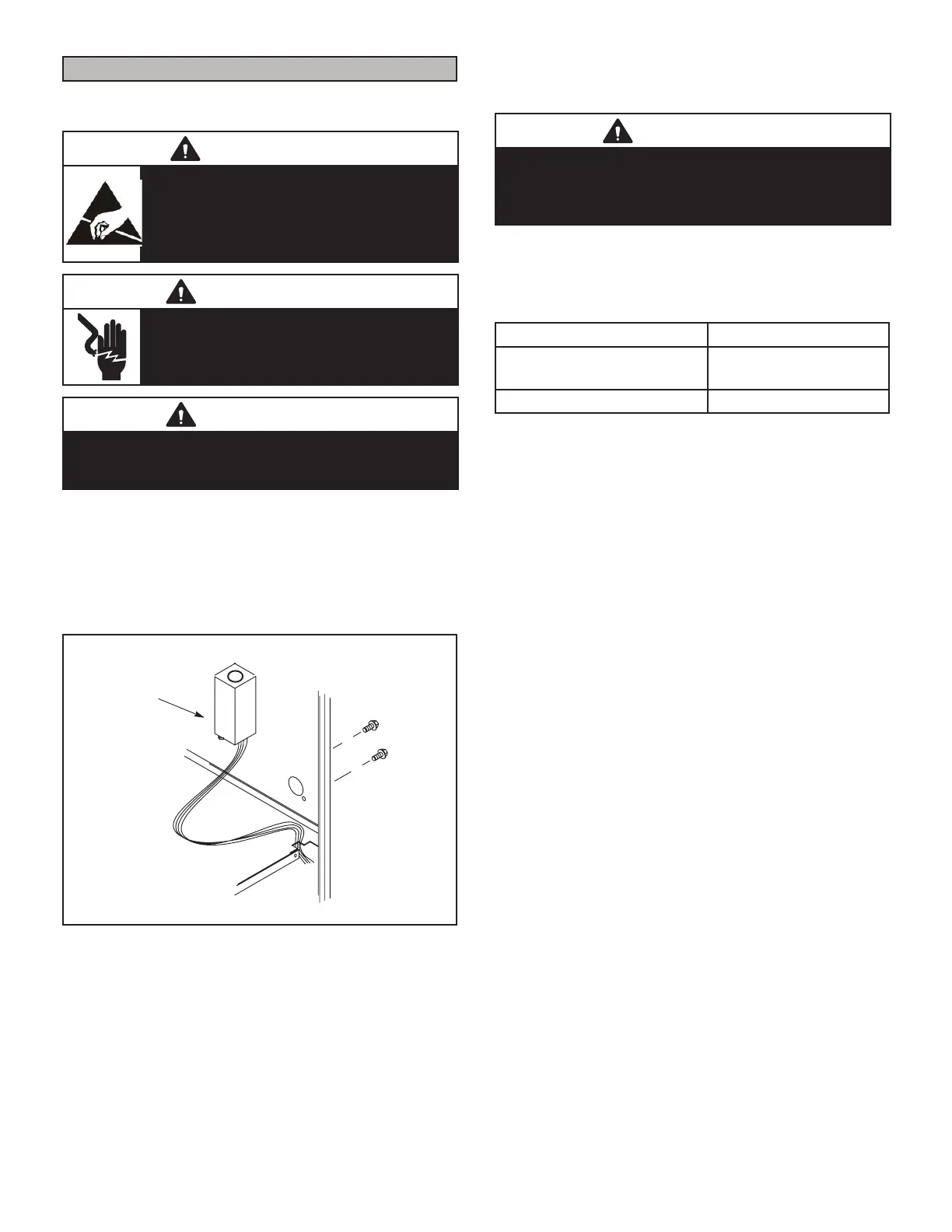
The unit is equipped with a eld make-up box on the left
hand side of the cabinet. The make-up box may be moved
to the right side of the furnace to facilitate installation. If
the make-up box is moved to the right side, clip the wire
ties that bundle the wires together. The excess wire must
be pulled into the blower compartment. Secure the excess
wire to the existing harness to protect it from damage.
INTERIOR MAKE-UP BOX INSTALLATION
MAKE-UP
BOX
Right Side
FIGURE 58
The power supply wiring must meet Class I restrictions.
Protected by either a fuse or circuit breaker, select circuit
protection and wire size according to unit nameplate.
CAUTION
Failure to use properly sized wiring and circuit breaker
may result in property damage. Size wiring and circuit
breaker(s) per Product Specications bulletin (EHB) and
unit rating plate.
NOTE - Unit nameplate states maximum current draw.
Maximum over-current protection allowed is shown in ta-
ble 10.
TABLE 10
ML296UHV Maximum Over-Current
045V36B, 070V36B,
090V348C
15
110V60C 20
Holes are on both sides of the furnace cabinet to facilitate
wiring.
Install a separate (properly sized) disconnect switch near
the furnace so that power can be turned o for servicing.
Before connecting the thermostat or the power wiring,
check to make sure the wires will be long enough for ser-
vicing at a later date. Remove the blower access panel to
check the length of the wire.
Complete the wiring connections to the equipment. Use
the provided unit wiring diagram and the eld wiring dia-
gram shown in gure 61. Use 18-gauge wire or larger that
is suitable for Class II rating for thermostat connections.
Electrically ground the unit according to local codes or, in
the absence of local codes, according to the current Na-
tional Electric Code (ANSI/NFPA No. 70). A green ground
wire is provided in the eld make-up box. NOTE - The
ML296UHV furnace contains electronic components that
are polarity sensitive. Make sure that the furnace is wired
correctly and is properly grounded.
One line voltage “EAC” 1/4” spade terminal is provided
on the furnace integrated control. Any electronic air M
cleaner or other accessory rated up to one amp can be
connected to this terminal with the neutral leg of the circuit
being connected to one of the provided neutral terminals.
See Figure 62 for control conguration. This terminal is
energized when the indoor blower is operating.
 Loading...