Page 14
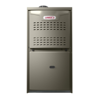
HORIZONTAL RIGHT POSITION
Side Vent Discharge
FIGURE 20
FLOW
AIR
Pressure Switch
Flue Transition
Collector Box
IMPORTANT
Do not use an unlined masonry chimney as the flue
for this appliance.
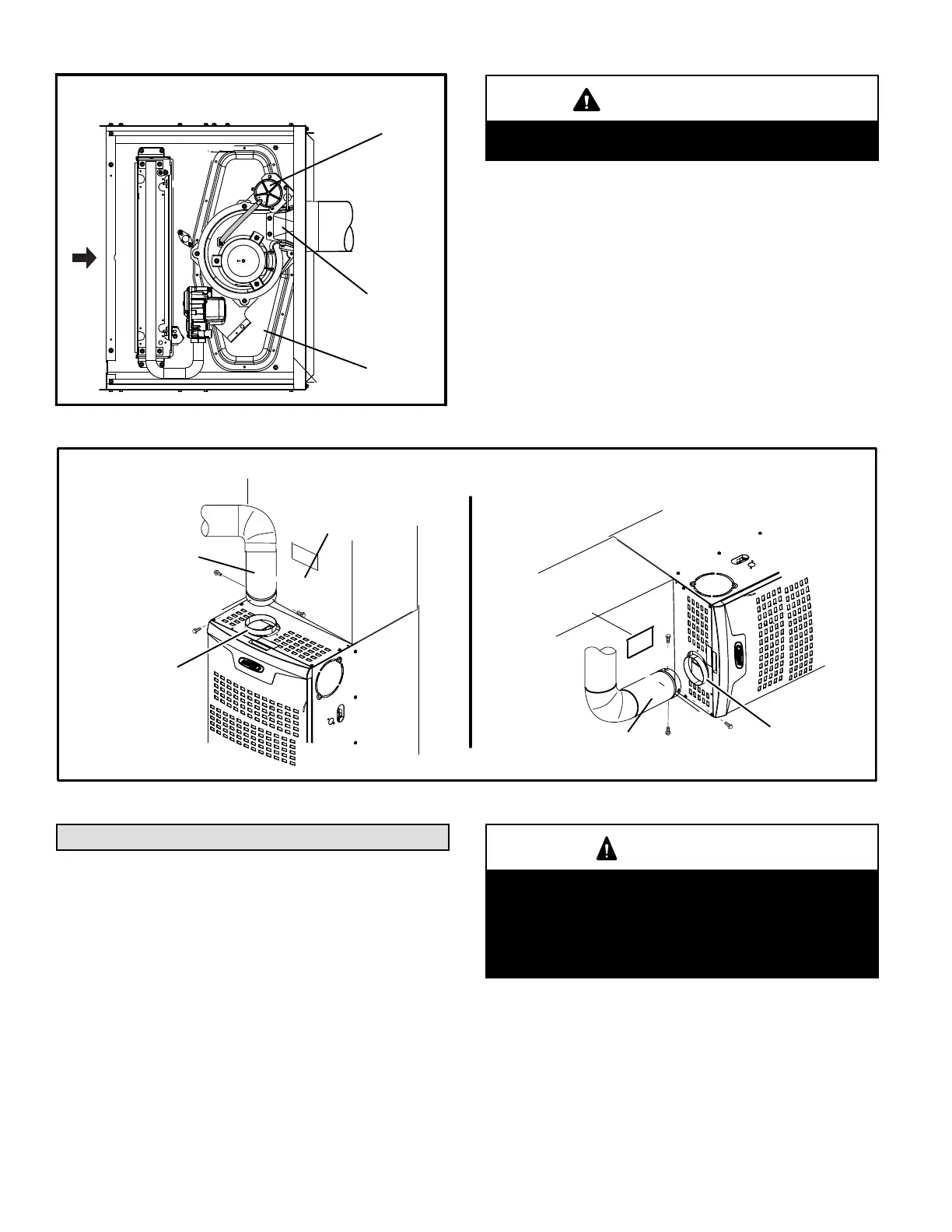
FIGURE 21
FLUE TRANSITION
COLLAR
VENT PIPE
(min. 6” length)
“DISCONNECTED VENT”
WARNING
STICKER
FLUE
TRANSITION
COLLAR
VENT CONNECTION UPFLOW AND HORIZONTAL POSITION
VENT PIPE
(min. 6” length)
“DISCONNECTED VENT”
WARNING
STICKER
Gas Piping
Refer to the current edition of the Australian Gas Instal
lation Code (AS/NZS5601) for gas piping requirements
and gas pipe sizing tables.
Gas supply piping should not allow more than 125 Pa
(0.5”W.C.) drop in pressure between gas meter and unit.
Supply gas pipe must not be smaller than unit gas connec
tion.
CAUTION
If a flexible gas connector is required or allowed by
the authority that has jurisdiction, black iron pipe
shall be installed at the gas valve and extend outside
the furnace cabinet. The flexible connector can then
be added between the black iron pipe and the gas
supply line.
 Loading...