Page 9
I-UNIT COMPONENTS
Unit components are shown in FIGURE 1. The gas valve,
combustion air inducer and burners can be accessed by
removing the access panel. Electrical components are in
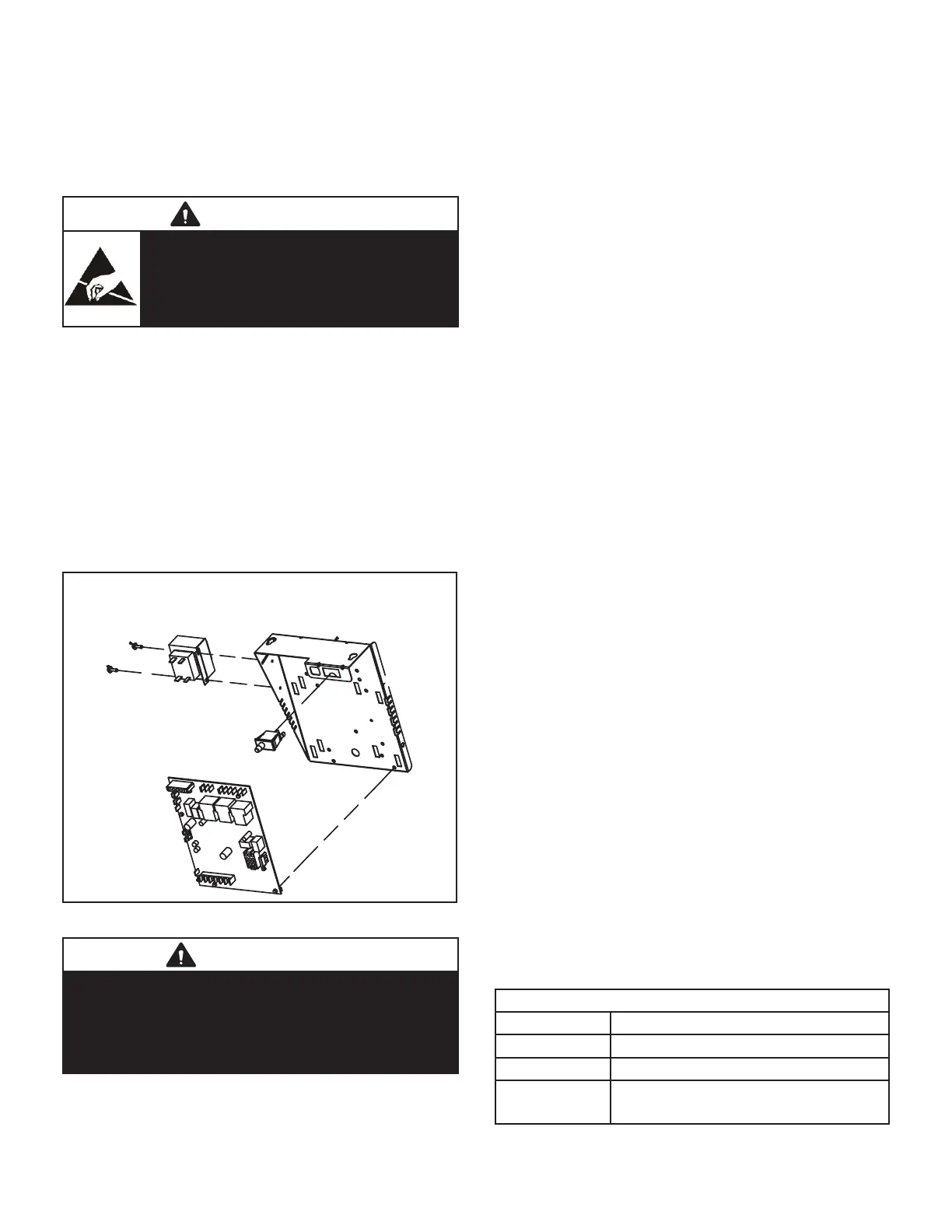
the control box (FIGURE 2) found in the blower section.
ELECTROSTATIC DISCHARGE (ESD)
Precautions and Procedures
CAUTION
Electrostatic discharge can aect electronic
components. Take precautions to neutralize
electrostatic charge by touching your hand
and tools to metal prior to handling the
control.
A- Control Box
1. Control Transformer (T1)
A transformer located in the control box provides power
to the low voltage section of the unit. Transformers on all
models are rated 40VA with a 120V primary and a 24V
secondary.
2. Door Interlock Switch (S51)
A door interlock switch rated 14A at 125VAC is wired in se-
ries with line voltage. When the inner blower access panel
is removed the unit will shut down.
Control Box Components
Integrated Control
Door Interlock Switch
Transformer
FIGURE 2
WARNING
Shock hazard.
Disconnect power before servicing. Integrated
control is not eld repairable. If control is inoperable,
simply replace entire control. Can cause injury
or death. Unsafe operation will result if repair is
attempted.
3. Integrated Control (A92)
Units are equipped with a two-stage, variable speed inte-
grated control. The system consists of a ignition / blower
control (FIGURE 3) with control pin designations in TABLE
3, TABLE 4 and 4 and ignitor. The control and ignitor work
in combination to ensure furnace ignition and ignitor dura-
bility. The control provides gas ignition, safety checks and
indoor blower control with two-stage gas heating. The fur-
nace combustion air inducer, gas valve and indoor blower
are controlled in response to various system inputs such
as thermostat signal, pressure and limit switch signal and
ame signal.
The furnace has a built-in, self-diagnostic capability. If a
system problem occurs, a fault code is shown by a red
LED on the control. The control continuously monitors its
own operation and the operation of the system. If a failure
occurs, the LED will indicate the failure code. The ash
codes are presented in TABLE 2.
Fault Code History Button
The control stores the last ve fault codes in memory. A
pushbutton switch is located on the control. When the
pushbutton switch is pressed and released, the control
ashes the stored fault codes. The most recent fault code
is ashed rst; the oldest fault code is ashed last. To
clear the fault code history, press and hold the pushbutton
switch in for more than 5 seconds before releasing.
Single Stage Thermostat Operation
The automatic heat staging option allows a single stage
thermostat to be used with two stage furnace models. To
activate this option, move the jumper pin (see FIGURE 3)
to desired setting (5 minutes or 10 minutes). The furnace
will start on 1st stage heat and stay at 1st stage heat for
the duration of the selected time before switching to 2nd
stage heat. W1 on the integrated control must be connect-
ed to W1 on the thermostat.
High Heat State LED
A green LED is provided on the control board to indicate
high heat state (see TABLE 1).
CFM LED
An amber LED is provided on the control board to display
CFM. To determine what CFM the motor is delivering at
any time, count the number of times the amber LED ash-
es. Each ash signies 100 CFM; count the ashes and
multiply by 100 to determine the actual CFM delivered (for
example: 5 ashes x 100 = 500 CFM).
TABLE 1
High Heat State Green LED
LED Status Description
LED O No demand for high heat
LED On High heat demand, operating normally
LED Flashing
High heat demand, high pressure
switch not closed
 Loading...