Do you have a question about the Lennox ML193UH and is the answer not in the manual?
Details limited warranty coverage for heat exchanger and other components over specified periods in residential and non-residential applications.
Describes the primary and secondary heat exchanger design, materials, and benefits for efficiency and airflow.
Details the construction of the secondary heat exchanger, including aluminum fins and stainless steel tubes, and its leak testing.
Highlights the aluminized steel inshot burners for efficient operation, proper air-gas mixing, and ease of service.
Details the unique, high-strength ceramic ignitor for long life, fast heat-up, and reliable ignition with low power usage.
Describes the 24-volt redundant combination gas control valve, integrating manual shut-off, automatic electric valve, and gas pressure regulation.
Explains the role of the shaded pole blower in prepurging the heat exchanger and venting flue products during the heating cycle.
Central control board managing furnace operations, including inducer control, pre/post-purge cycles, ignition, and flame sensing.
Describes the blower's static and dynamic balance, resilient mounting, ease of service, and speed adjustment via the control board.
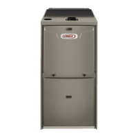
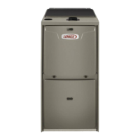
Details the low-profile, narrow width, heavy-gauge steel construction, pre-painted finish, and foil-faced insulation for efficient installation and operation.
Details the ML193UH model numbering system, including unit type, stages, AFUE, configuration, input, blower, and cabinet width.
Presents AFUE, Input/Output Btuh, Temperature Rise Range, and Gas Manifold Pressure for various models.
Specifies minimum required clearances in inches (mm) for sides, rear, top/plenum, front, and floor installations.
Tables detailing maximum allowable vent lengths in feet for standard terminations at elevations up to 10,000 ft. based on input size and pipe diameter.
Tables specifying maximum vent lengths in feet for concentric terminations at elevations up to 10,000 ft. by input size and pipe diameter.
Provides key dimensions (A, B, C, D) in inches and millimeters for various ML193UH models in the upflow configuration, with diagrams.
Presents dimensions (A, B, C, D) in inches and millimeters for various ML193UH models in both left-hand and right-hand horizontal discharge configurations.
Lists combined dimensions (A, B) in inches and millimeters for various ML193UH furnaces when paired with specific CX34 and C33 coils in upflow configurations.
Provides combined dimensions (A, B) in inches and millimeters for specific ML193UH furnaces with CH33 coils in horizontal configurations.
Presents detailed blower performance data (Air Volume vs. Watts) for various external static pressures across different speed settings for multiple furnace models.
| Efficiency | 93% AFUE |
|---|---|
| Heating Stages | Single-stage |
| Blower Motor | PSC |
| Energy Star Certified | No |
| Gas Valve | Single-stage |
| Ignition System | Hot Surface Ignition |
| Blower Motor Type | PSC |
| Ignition Type | Hot Surface Ignition |
| Fuel Type | Natural Gas or Propane |
| Warranty | 5-Year Limited Warranty on covered components |
| Stages of Heat | Single-stage |
| Heating Capacity | 44, 000-132, 000 BTU/h |