EasyManua.ls Logo

Lennox ML193UH070P36B

Lennox ML193UH070P36B
55 pages
To Next Page IconTo Next Page
Loading...
Page 1
© 2014 Lennox Industries Inc.
Litho U.S.A.
Corp. 1025-L5
ML193UH
Service Literature
Revised 03-2014
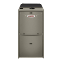
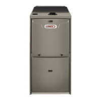
ML193UH SERIES UNITS
ML193UH series units are high-efficiency gas furnaces
manufactured with Lennox DuralokPlust aluminized steel
clamshell-type heat exchangers, with a stainless steel con
densing coil. ML193UH units are available in heating input
capacities of 44,000 to 132,000 Btuh (13 to 38.6 kW) and
cooling applications from 2 through 5 tons (7.0 through
17.6 kW). Refer to Engineering Handbook for proper siz
ing.
Units are factory equipped for use with natural gas. A kit is
available for conversion to LPG operation. All ML193UH
units are equipped with a hot surface ignition system. The
gas valve is redundant to assure safety shut-off as required
by C.S.A.
The heat exchanger, burners and manifold assembly can
be removed for inspection and service. The maintenance
section gives a detailed description on how this is done.
All specifications are subject to change. Procedures out
lined in this manual are presented as a recommendation
only and do not supersede or replace local or state codes.
WARNING
Electric shock hazard. Can cause injury
or death. Before attempting to perform
any service or maintenance, turn the
electrical power to unit OFF at discon
nect switch(es). Unit may have multiple
power supplies.
Table of Contents
Specifications 2.................................
Optional Accessories 3..........................
Blower Performance Data 4......................
I-Unit Components 7............................
II Placement and Installation 19....................
III-Start-Up 40...................................
IV-Heating System Service Checks 41..............
V-Typical Operating Conditions 43.................
VI-Maintenance 44...............................
VII-Sequence of Operation and Flow Charts 47......
WARNING
Improper installation, adjustment, alteration, service
or maintenance can cause property damage, person
al injury or loss of life. Installation and service must
be performed by a licensed professional HVAC in
staller (or equivalent), service agency or the gas sup
plier.
WARNING
Sharp edges.
Be careful when servicing unit to avoid sharp edges
which may result in personal injury.

Questions and Answers:

Lennox ML193UH070P36B Specifications

General IconGeneral
BrandLennox
ModelML193UH070P36B
CategoryFurnace
LanguageEnglish

Summary

Unit Information

Series Units Overview

Provides an overview of the ML193UH series furnaces, their capabilities, and features.

Safety Warnings

Highlights critical safety precautions, including electrical shock and sharp edges.

Specifications

Optional Accessories and Gas Heat Accessories

Installation Clearances

Details required clearances for installation around the unit.

Blower Performance Data

Parts Identification

Component Locations

Identifies major components of the ML193UH furnace via a diagram.

Unit Components

Control Box Components

Details the transformer, door interlock switch, and ignition control within the control box.

Electronic Ignition System

Explains the integrated control, ignitor, and flame sensor functionality.

Fan and Control Terminals

Fan Control Settings

Describes how to adjust the fan off delay settings for comfort.

Integrated Control Terminal Designations

Lists and explains the terminal designations on the integrated control board.

Diagnostic Codes

Integrated Ignition Control Details

Ignition Control Terminal Designations

Provides terminal designations for 4-pin and 12-pin connectors.

Troubleshooting Codes

Lists diagnostic codes and their corresponding LED status for troubleshooting.

Fan Time Control and Twinning

Fan Time Adjustments

Explains how to adjust heating fan on/off times and cooling fan settings.

Furnace Twinning Configuration

Details the process and requirements for twinning two furnaces.

Twinning Field Wiring

Heating Components Identification

Ignitor, Flame Sensor, and Rollout Switches

Identifies and describes the ignitor, flame sensor, and rollout switches.

Ignitor Checks

Key Component Details

Primary Limit, Heat Exchanger, and Burners

Describes the function and characteristics of the primary limit, heat exchanger, and burners.

Gas Valve Function

Explains the operation and replacement of the gas valve.

Combustion Air System Components

Combustion Air Inducer and Header Box

Details the combustion air inducer, its housing, and associated components.

Combustion Air Pressure Switch

Explains the function and operation of the combustion air pressure switch.

Pressure Measurement and Blower Compartment

Measuring Pressure Differential

Guides on how to measure pressure differential for system checks.

Blower Motor and Capacitor

Describes the blower motor and capacitor within the blower compartment.

Placement and Installation: Pipe Specifications

Piping and Fittings Specifications

Lists approved piping and fitting materials and specifications for venting.

Outdoor Termination Usage and Cementing

Outdoor Termination Usage Table

Details outdoor termination options based on input size and vent style.

Joint Cementing Procedure

Provides step-by-step instructions for cementing pipe joints.

Venting Practices and Guidelines

General Venting Practices

Covers pipe suspension, wall thickness, and general venting considerations.

Confined Space Equipment

Shows equipment setup for confined spaces (attic/crawlspace).

Vent Piping Guidelines and Sizing

Vent Piping and Termination Guidelines

Explains vent pipe options and installation rules.

Piping Size Process

A step-by-step guide to sizing vent pipe diameter based on various factors.

Maximum Vent Length Tables

Exhaust Pipe Connections

UpflowNon-Direct Vent Exhaust

Illustrates typical exhaust pipe connections for upflow direct or non-direct vent.

Horizontal Exhaust Pipe Connections

Shows typical exhaust pipe connections for horizontal direct or non-direct vent.

Air Intake Pipe Connections

Upflow Direct Vent Intake

Illustrates typical air intake pipe connections for upflow direct vent applications.

Horizontal Direct Vent Intake

Shows typical air intake pipe connections for horizontal direct vent applications.

Intake Piping Details

Direct Vent Intake Piping

Instructions for routing intake piping in direct vent applications.

Non-Direct Vent Intake Piping

Guidelines for intake piping in non-direct vent applications.

Vent Termination Guidelines

General Vent Termination Rules

Covers general rules for vent terminations, including location and clearances.

Maximum Uninsulated Vent Lengths

Vent Termination Clearances (Non-Direct Vent)

Vent Termination Clearances (Direct Vent)

Direct Vent Piping Terminations

Exhaust Pipe Termination Size Reduction

Table specifying exhaust pipe size reductions for different models.

Field Fabricated and Alternate Terminations

Field Fabricated Wall Termination

Instructions and diagrams for field-fabricated wall vent terminations.

Alternate Elbow Terminations

Shows alternative termination methods using tees and elbows.

Non-Direct Vent Exhaust Terminations

Condensate Piping Installation

Explains the routing and installation of condensate piping.

TrapDrain Assembly (34 Connection)

TrapDrain Assembly (12 Connection)

Start-Up Procedures

Preliminary and Seasonal Checks

Covers initial checks before starting the furnace, including wiring and gas.

Failure To Operate Diagnosis

Lists common issues and checks when the unit fails to operate.

Heating System Service Checks

Gas Piping and Testing

Details gas piping requirements, leak testing, and pressure checks.

Manifold Pressure and Combustion

Covers manifold pressure measurement and proper combustion checks.

High Altitude Adjustments

Operating Characteristics and Testing

Flame Signal Measurement

Explains how to measure the flame signal using a transducer.

Blower and Temperature Adjustments

Covers blower operation, adjustment, and temperature rise measurement.

External Static Pressure Testing

Details the procedure for measuring external static pressure.

Maintenance Procedures

Filter Inspection and Replacement

Guidelines for inspecting and replacing air filters for optimal performance.

Winterizing and Condensate Trap Care

Instructions for preparing the unit for winter and maintaining condensate traps.

Condensate Hose Screen Cleaning

Steps for cleaning condensate hose screens to prevent blockages.

Cleaning the Heat Exchanger

Cleaning the Burner Assembly

Wiring Diagram and Heating Sequence

ML193 UH Wiring Diagram (Integrated Control 100973)

Provides a wiring diagram for units with integrated control 100973.

Heating Sequence of Operation

Explains the step-by-step process for furnace heating operation.

Cooling Sequence of Operation

Continuous Fan Sequence

Wiring Diagram (Integrated Control 103085)

Related product manuals