EasyManua.ls Logo

Lennox ML193UH045XE36B

Lennox ML193UH045XE36B
52 pages
To Next Page IconTo Next Page
Loading...
Page 1
© 2019 Lennox Industries Inc.
Litho U.S.A.
Corp. 1905
ML193UHE
Service Literature
ML193UHE SERIES UNITS
ML193UHE series units are high-efficiency gas fur
naces manufactured with Lennox DuralokPlust alumi
nized steel clamshell-type heat exchangers, with a stainless
steel condensing coil. ML193UHE units are available in
heating input capacities of 30,000 to 110,000 Btuh (8.8 to
32.2 kW) and cooling applications from 2 through 5 tons (7.0
through 17.6 kW). Refer to Engineering Handbook for proper
sizing.
Units are factory equipped for use with natural gas. A kit is
available for conversion to LPG operation. All ML193UHE
units are equipped with a hot surface ignition system. The
gas valve is redundant to assure safety shut-off as re
quired by C.S.A.
The heat exchanger, burners and manifold assembly can be
removed for inspection and service. The maintenance section
gives a detailed description on how this is done.
The ML193UHE can be “twinned” with a second unit. See
twinning kit 16W72 for information for two units to operate
as one, in a shared duct system controlled by a single ther
mostat.
All specifications are subject to change. Procedures outlined
in this manual are presented as a recommendation only
and do not supersede or replace local or state codes.
WARNING
Electric shock hazard. Can cause injury
or death. Before attempting to perform
any service or maintenance, turn the
electrical power to unit OFF at discon
nect switch(es). Unit may have multiple
power supplies.
Table of Contents
Specifications 2.................................
Optional Accessories 4..........................
Blower Performance Data 5......................
I-Unit Components 7............................
II Placement and Installation 20....................
III-Start-Up 39...................................
IV-Heating System Service Checks 40..............
V-Typical Operating Conditions 44.................
VI-Maintenance 45...............................
VII-Sequence of Operation and Flow Charts 48......
WARNING
Improper installation, adjustment, alteration, service
or maintenance can cause property damage, person
al injury or loss of life. Installation and service must
be performed by a licensed professional HVAC in
staller (or equivalent), service agency or the gas sup
plier.
CAUTION
As with any mechanical equipment, contact with
sharp sheet metal edges can result in personal in
jury. Take care while handling this equipment and
wear gloves and protective clothing.

Table of Contents

Other manuals for Lennox ML193UH045XE36B

Question and Answer IconNeed help?

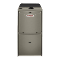
Do you have a question about the Lennox ML193UH045XE36B and is the answer not in the manual?

Lennox ML193UH045XE36B Specifications

General IconGeneral
BrandLennox
ModelML193UH045XE36B
CategoryFurnace
Efficiency93% AFUE
IgnitionHot Surface Ignition
Weight120 lbs
BTU Input45, 000 BTU/h
StagesSingle Stage
Warranty5-Year Limited Warranty on covered components
Dimensions17.5" W x 28" D

Summary

ML193 UHE SERIES UNITS

SPECIFICATIONS

BLOWER DATA

ML193 UHE PARTS IDENTIFICATION

I-UNIT COMPONENTS

A-Control Box Components

Identification of components within the furnace control box.

4. Integrated Ignition Control (A92)

Details on the hot surface ignition system and its integrated control module.

B-Heating Components

C- Blower Compartment

II-PLACEMENT AND INSTALLATION

Venting Practices

Intake Piping

Piping Size Process

Step-by-step process for correctly sizing the furnace vent pipe diameter.

TYPICAL EXHAUST AND INTAKE PIPE CONNECTIONS IN UPFLOW DIRECT OR NON-DIRECT VENT APPLICATIONS

TYPICAL EXHAUST AND INTAKE PIPE CONNECTIONS IN HORIZONTAL DIRECT OR NON-DIRECT VENT APPLICATIONS

General Guidelines for Vent Terminations

VENT TERMINATION CLEARANCES FOR NON-DIRECT VENT INSTALLATIONS

VENT TERMINATION CLEARANCES FOR DIRECT VENT INSTALLATIONS

Details of Intake and Exhaust Piping Terminations for Direct Vent Installations

Condensate Piping

III-START-UP

A-Preliminary and Seasonal Checks

Pre-startup checks including electrical, traps, and seasonal inspections.

B-Heating Start-Up

Procedures for initiating the heating operation of the furnace.

Priming Condensate Trap

Steps to prime the condensate trap to ensure proper drainage before operation.

Gas Valve Operation

Instructions for operating the gas valve and safety precautions.

Failure To Operate

Troubleshooting checklist for common issues when the unit fails to operate.

IV-HEATING SYSTEM SERVICE CHECKS

B-Gas Piping

Guidelines and warnings related to gas piping installation and connections.

C-Testing Gas Piping

Procedures for testing gas piping connections for leaks and pressure.

D-Testing Gas Supply Pressure

Methods for testing gas supply pressure and gas flow rates.

Supply Pressure Measurement

Steps for measuring supply gas pressure at the gas valve.

Manifold Pressure Measurement

Procedure for measuring the gas manifold pressure.

E-Proper Combustion

F-High Altitude

G- Proper Ground and Voltage

V-TYPICAL OPERATING CHARACTERISTICS

A-Blower Operation and Adjustment

General procedures for blower operation and adjustments based on thermostat settings.

VI-MAINTENANCE

Cleaning Heat Exchanger

Cleaning the Burner Assembly

VII-WIRING DIAGRAM AND SEQUENCE OF OPERATION

Troubleshooting: Heating Sequence of Operation

Troubleshooting: Cooling Sequence of Operation

Troubleshooting: Continuous Fan Accessories Sequence of Operation

Related product manuals