EasyManua.ls Logo

Lennox MPA012S4S-1P User Manual

Lennox MPA012S4S-1P
258 pages
To Next Page IconTo Next Page
Page #1 background imageLoading...
Page #1 background image
Lennox Mini-Split Service Manual / Page 1
LENNOX MINI-SPLIT SYSTEMS
SERVICE MANUAL

Table of Contents

Other manuals for Lennox MPA012S4S-1P

Question and Answer IconNeed help?

Do you have a question about the Lennox MPA012S4S-1P and is the answer not in the manual?

Lennox MPA012S4S-1P Specifications

General IconGeneral
Cooling Capacity12, 000 BTU/h
EER11.5
RefrigerantR-410A
Voltage208/230V
Phase1
Compressor TypeInverter

Summary

Section 1 - Outdoor Unit Data

Section 1.1 - MPA Single Zone Condensing Units

Specifications and model number identification for MPA single zone condensing units.

Section 1.2 - MPA Multi-Zone Condensing Unit

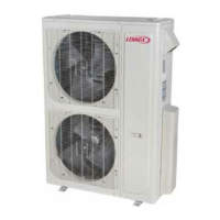
Specifications for MPA multi-zone condensing units, covering 1.5 to 4 ton models.

Section 2 - Indoor Unit Data

Section 2.1 - M22A Compact Cassette Unit

Details on M22A compact cassette indoor units, including specs, sound, and air throw data.

Section 2.2 - M33A Cassette Unit

Specifications and model identification for M33A cassette indoor units.

Section 2.3 - MMDA Ducted Unit

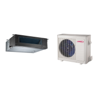
Information on MMDA medium static ducted indoor units, including specs and blower data.

Section 2.4 - MWMA Wall Mounted Unit

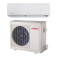
Specifications and model identification for MWMA wall-mounted indoor units.

Section 2.5 - MCFA Ceiling/Floor Unit

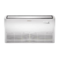
Data for MCFA ceiling/floor mount indoor units, including dimensions and specifications.

Section 3 - Installation Dimensions of Outdoor Units

Section 3.1 - Single Zone Installation Dimensions

Provides installation dimension details for single zone MPA outdoor units.

Section 3.2 - Multi-Zone Installation Dimensions

Installation dimension details for multi-zone MPA outdoor units.

Section 3.3 - MPA Outdoor Unit Clearances

Specifies the required clearances for MPA outdoor units for proper operation.

Section 4 - Installation Dimensions of Indoor Units

Section 4.1 - M22A Compact Cassette

Dimensions and clearances for M22A compact cassette indoor units.

Section 4.2 - M33A Cassette Unit

Dimensions and clearances for M33A cassette indoor units.

Section 4.3 - MMDA Ducted Unit

Installation dimensions and clearances for MMDA ducted indoor units.

Section 4.4 - MWMA Wall Mounted Unit

Dimensions and clearances for MWMA wall-mounted indoor units.

Section 4.5 - MCFA Ceiling/Floor Unit

Details on MCFA ceiling/floor unit dimensions and clearances.

Section 5 - Indoor Unit Combinations

Multi-Zone System Combinations

Details on combining indoor units with outdoor units for multi-zone systems.

Section 6 - Refrigeration Pipe Work

Section 6.1 - Single Zone Refrigerant Cycle Diagram

Illustrates the refrigerant cycle for single zone systems.

Section 6.2 - Multi-Zone Refrigerant Cycle Diagram

Illustrates the refrigerant cycle for multi-zone systems.

Section 6.1 - Refrigeration Pipe Work for Singe Zone Systems

Covers pipe work requirements and limitations for single zone systems.

Section 6.2 - Refrigeration Pipe Work for Multi-Zone Systems

Details pipe work and connections for multi-zone systems.

Section 7 - Power Wiring for Outdoor & Indoor Units

Section 8 - Data Wiring 036 & 048 Sizes Only

Section 9 - Wiring Diagrams

Section 9.1 - Single Zone Wiring Diagrams

Wiring diagrams for various single zone outdoor units.

Section 9.1 - Multi-Zone Wiring Diagrams

Wiring diagrams for multi-zone outdoor units.

Section 9.1 - Indoor Unit Wiring Diagrams

Wiring diagrams for different types of indoor units.

Section 10 - Condensate Pipe Work Installation Data

Section 10.1 - Outdoor Unit Condensate Pipe

Requirements for outdoor unit condensate pipe installation and drainage.

Section 10.2 - Indoor Unit Gravity Drain

Details on gravity drain requirements for MWMA and MCFA indoor units.

Section 10.3 - Indoor Unit Lift Pump

Information on indoor unit lift pump and condensate piping for MMDA, M22A/M33A.

Section 11 - Controls

Section 11.1 - M0STAT60Q Wireless Controller

Operation and features of the M0STAT60Q wireless remote controller.

Section 11.2 - M0STAT61Q-1 Wired Controller

Features and operation of the M0STAT61Q-1 wired controller.

Section 12 - Start Up

Section 12.1 - General Start Up Information

General information and procedures for starting up the system.

Outdoor Unit Spot Check Function

Procedure for checking outdoor unit states using the digital display.

Outdoor unit’s digital display tube

Explanation of the outdoor unit's digital display tube functions.

Section 13 - Fault Codes

Section 13.1 - Quick Reference Guide - Fault Codes

Quick reference tables for fault codes across different unit types.

Section 13.2 - Troubleshooting Single Zone Outdoor Units

Troubleshooting guide for single zone outdoor units based on flash codes.

Section 13.3 - Troubleshooting Multi-Zone Outdoor Units

Troubleshooting guide for multi-zone outdoor units and their fault codes.

Section 13.4 - Indoor Unit Fault Codes

Fault code information and troubleshooting for all indoor units.

Appendix 1 - Temperature Sensor Resistance Value Table (°C--K)

Appendix 2 - Discharge Temperature Sensor Table (°C--K)

Appendix 3 - Celsius to Fahrenheit Conversion Table

Compressor Check

IPM Check

AC Fan Motor

4-Way Valve

EXV Check

Electronic Functions Abbreviations

Electronic Control Working Environment

Main Protection

Compressor Preheating Functions

Compressor Crankcase Heater

Capacity Request Calculation

Defrost Control

Outdoor Fan Control

Cooling Mode

Controls outdoor fan speed in cooling mode based on ambient temperature.

Heating Mode

Controls outdoor fan speed in heating mode based on ambient temperature.

Four-Way Valve Control

Electronic Expansion Valve (EXV) Control

Related product manuals