Page 63
Corp. 1244-L9
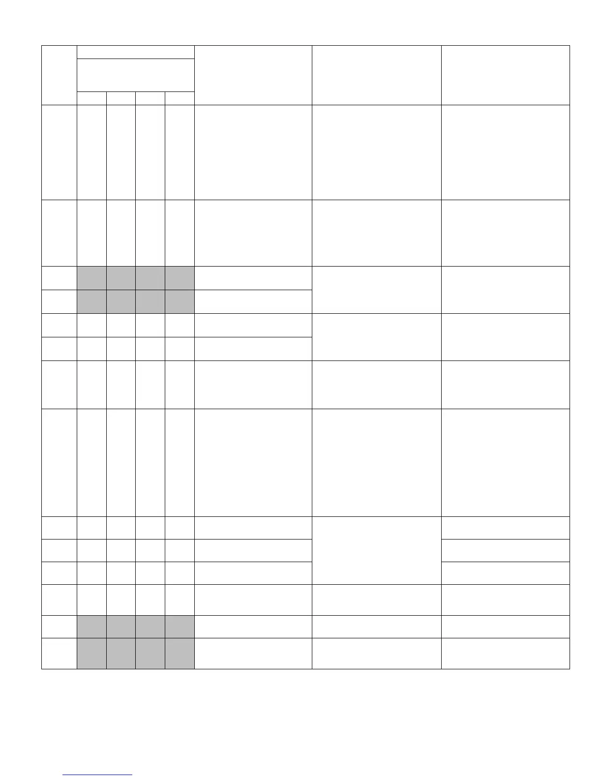
Continued — 18 - 24 kBtu System Status or Error Codes — Indoor Character Display and Outdoor LEDs
Indoor
Unit
Display
Outdoor Unit LED Status
Error Description System Status
Troubleshooting for Possible
Causes
This unit has three display
status indicators
o OFF
n ON ® BLINKS
D5 D6 D16 D30
EU
n n n ®
Intelligent Power Module
protection limit
System will continue to run; how
ever at reduced compressor speed
until issue is corrected.
Intelligent Power Module
protection limit error can result
from any of the following:
S Loss of cooling to the heat sink
S Low voltage
S High ambient temperature
S Loose screws fastening the out
door control to the heat sink
Check all and correct, if necessary.
See figure 92 for troubleshooting.
FH
n n n
o
Anti-freezing upper and lower
limit range
System will continue to run; how
ever at reduced compressor speed
until issue is corrected.
The indoor coil sensor (RT2) moni
tors the coil temperature continu
ously. Any time the coil tempera
ture falls between 42.8ºF (6ºC)
and 30.2ºF (-1ºC), the micropro
cessor will initiate anti-freeze
protection operation.
F1
Indoor ambient sensor (RT1)
open or short-circuited
Cooling and dehumidify will contin
ued to operate as well as indoor
fan. Heating will not operate.
Sensor input is out of acceptable
input range. Check sensor for
proper resistance. Replace sensor
if shorted, open or out-of-calibra
tion.
F2
Indoor coil sensor (RT2) open
or short-circuited
F3 o o
® n
Outdoor ambient sensor (RT4)
open or short-circuited
All system functions are termi
nated except indoor fan.
Sensor input is out of acceptable
input range. Check sensor for
proper resistance. Replace sensor
if shorted, open or out-of-calibra
tion.
F4 o o
®
o
Outdoor coil sensor (RT3) open
or short-circuited
F5 o o
® ®
Discharge line sensor (RT5)
error
All system functions except indoor
fan will be terminated after 3-min
ute delay.
Sensor input is out of acceptable
input range. Check sensor for
proper resistance. Replace sensor
if shorted, open or out-of-calibra
tion.
F6
n
o
® ®
Compressor overload limit
issue
Normal operational state with com
pressor speed automatically adjust
for operational conditions. System
will continue to operate at reduced
compressor speed until issue is
corrected.
S Check outdoor ambient air tem
perature. Could be too high.
S Check for locked compressor ro
tor
S Check for locked refrigeration cir
cuit (capillary tubes for example)
S Check for blocked or restricted
outdoor air flow. Clear, if neces
sary.
S Check for low refrigerant charge.
See unit information manual for
further information.
F8
n n
o
n
High current limit issue
System will continue but will re
duce compressor speed to correct
issue
Check input voltage. It may be ei
ther too low or too high.
F9
n n
o o Discharge temperature too high
Discharge line temperature is high.
See figure 72.
HC o
n ® ®
Power factor correction protec
tion
See unit information manual for
further information.
H0
n
o
® ®
Heating mode anti-high
temperature protection
System will continue operation at a
reduced compressor speed until
issue is resolved.
See unit information manual for
further information.
H1 Defrosting (heat pump only) Normal operation
Normal operation to defrost out
door coil.
H2 Electrostatic protection
System protection feature. All sys
tem functions are terminated ex
cept indoor fan.
Excessive electrostatic charge
present. Correct, if possible.
 Loading...