Page 4
Start-Up & Operation Information
WARNING
If you do not follow these instructions exactly, a re
or explosion may result causing property damage,
personal injury or death.
BEFORE PLACING THE UNIT INTO OPERATION, smell
all around the appliance area for gas. Be sure to smell
next to the oor because some gas is heavier than air and
will settle on the oor.
The gas valve on the SLP99DF is equipped with a gas
control switch. Use only your hand to move the control
switch. Never use tools. If the switch will not move by
hand, do not try to repair it. Call a licensed professional
service technician (or equivalent). Force or attempted re-
pair may result in a re or explosion.
Placing the SLP99DF furnace into operation:
SLP99DF units are equipped with a SureLight
®
ign tion
system. Do not attempt to manually light burners on this
furnace. Each time the thermostat calls for heat, the burn-
ers will automatically light. The ignitor does not get hot
when there is no call for heat on units with SureLight®
ignition system.
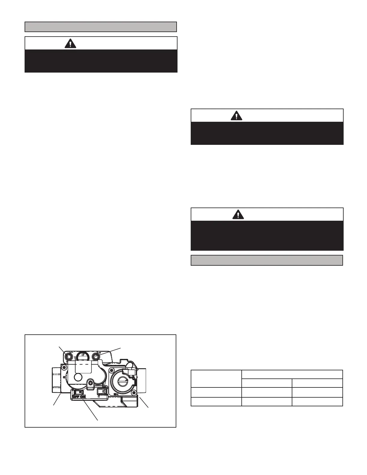
Operating the Gas Valve (Figure 2)
1 - STOP! Read the safety information at the beginning
of this section.
2 - Set the thermostat to the lowest setting.
3 - Turn o all electrical power to the unit.
4 - This furnace is equipped with an ignition device
which automatically lights the burners. Do not try to
light the burners by hand.
5 - Remove the outer access panel.
6 - Move the gas valve switch to the OFF position
gure 2.
7 - Wait ve minutes to clear out any gas. If you then
smell gas, STOP! Immediately call your gas supplier
from neighbor’s phone. Follow the gas supplier’s
instructions. If you do not smell gas go to next step.
NEGATIVE AIR
PRESSURE PORT
POSITIVE AIR
PRESSURE PORT
MANIFOLD
PRESSURE TAP
INLET
OUTLET
SUPPLY
PRESSURE
TAP
GAS VALVE SHOWN IN THE ON POSITION
FIGURE 2
8 - Move gas valve switch to ON position. See gure 2.
9 - Replace the outer access panel.
10 - Tur n on all electrical power to to the unit
11 - Se t the thermostat to desired setting.
NOTE - When unit is initially started, steps 1 through
11 may need to be repeated to purge air from gas line.
12 - If the appliance will not operate, follow the section
“Turning O Gas to the Unit” and call your service
technician or gas supplier.
Turning O Gas to the Unit
WARNING
If overheating occurs or if gas supply fails to shut
o, shut o the manual gas valve to the furnace
before shutting o electrical supply.
1 - Set the th ermostat to the lowest setting.
2 - Turn o all electrical power to the unit if service is to
be performed.
3 - Remove the outer access panel.
4 - Move the gas valve switch to the OFF position.
5 - Replace the outer access panel.
CAUTION
Do not set thermostat below 60F (16C) in heating
mode. Setting below 60F (16C) reduces the number
of heating cycles. Damage to the unit may occur that
is not covered by the warranty.
Filters
All SLP99DF lters are installed external to the unit. Filters
should be inspected monthly. Clean or replace the lter(s)
when necessary to ensure proper furnace operation. A l-
ter must be in place when the unit is operating. See
table 1 for recommended lter sizes.
NOTE - Use replacement lters that are similar in size
and eciency ratings to those originally provided by the
installing contractor. Use of replacement lters with higher
ltration ratings may restrict air ow to the furnace. This
may result in reduced unit eciency, as well as premature
blower motor failure.
The lter access panel must also be in place and properly
secured during unit operation.
TABLE 1
Furnace
Cabinet Width
Filter Size
Side Return Bottom Return
17-1/2” 16 x 25 x 1 (1) 16 x 25 x 1 (1)
21-1/2” 16 x 25 x 1 (1) 16 x 25 x 1 (1)

 Loading...


