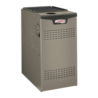
Do you have a question about the Lennox SIGNATURE SLP99DFV and is the answer not in the manual?
| Model | SLP99DFV |
|---|---|
| Type | Gas Furnace |
| Efficiency Rating | Up to 99% AFUE |
| Stages | Modulating |
| Blower Motor | Variable speed |
| Fuel Type | Natural Gas |
| Warranty | 10-Year Limited Warranty on covered components; Limited Lifetime Warranty on heat exchanger |
Details the physical measurements and key dimensions of the furnace unit.
Illustrates and labels the main components and their locations within the furnace.
Describes the furnace's variable-capacity, variable-speed integrated control and its capabilities.
Outlines critical safety warnings and cautions for installation and operation.
Provides guidelines for installing the furnace in conjunction with a cooling coil to prevent condensation.
Specifies conditions and criteria for using the furnace as a temporary construction heater.
Offers general recommendations for furnace placement and installation considerations.
Details critical steps and warnings for setting up the furnace equipment correctly.
Provides instructions for installing the furnace on non-combustible flooring.
Details installation requirements for mounting the furnace on combustible flooring.
Describes how to install the furnace on a cooling coil cabinet.
Explains how to properly connect the return air opening for downflow unit installations.
Specifies filter requirements and provides guidance on selecting the correct filter size.
Details the installation and purpose of the discharge air temperature sensor.
Lists approved materials and specifications for vent piping and associated fittings.
Explains how to configure venting options, including side venting.
Provides detailed steps for properly cementing vent pipe joints using solvent cement.
Outlines best practices and guidelines for vent pipe installation and routing.
Describes the process and factors involved in determining the correct vent pipe size.
Details the steps for attaching the flue coupling to the furnace top panel.
Illustrates typical exhaust pipe connections for right side vent configurations.
Illustrates typical air intake pipe connections for right side vent configurations.
Specifies required clearances for vent terminations in USA and Canada installations.
Provides guidance for venting through crawl spaces and extended horizontal runs.
Offers general advice and considerations for direct vent termination locations and clearances.
Details specific requirements and configurations for direct vent intake and exhaust piping terminations.
Illustrates concentric rooftop termination kits and their installation requirements.
Illustrates concentric wall termination kits and their installation requirements.
Describes how to apply direct vent configurations when using an existing chimney.
Provides dimensions and guidelines for field-fabricated wall vent terminations.
Details alternative vent termination methods using tee and 45-degree elbows.
Provides instructions for installing the condensate trap and piping for proper drainage.
Illustrates separate drain configurations for furnace and evaporator coil.
Illustrates common drain configurations for furnace and evaporator coil.
Details the assembly of condensate traps and drain lines using 1/2" or 3/4" PVC piping.
Covers essential safety warnings, torque specifications, and routing for gas piping.
Explains how to perform a leak check on all field-installed gas piping connections.
Provides safety warnings and procedures for removing a furnace from a common vent system.
Details electrical safety, wiring requirements, grounding, and circuit breaker sizing.
Guides the selection and setup of compatible thermostats for optimal furnace operation.
Explains how to set and adjust indoor blower speeds for heating and cooling modes.
Illustrates wiring connections for a communicating furnace with a non-communicating outdoor unit.
Illustrates wiring connections for a communicating furnace with a communicating outdoor unit.
Shows wiring diagrams for optional accessories used with communicating systems.
Details field wiring connections for non-communicating thermostat applications.
Continues detailing field wiring connections for non-communicating thermostat applications.
Details thermostat wiring for dual fuel heat pump applications.
Explains the integrated control board, its features, and terminal connections.
Provides DIP switch settings for non-communicating thermostats based on furnace operation.
Details DIP switch settings for controlling heating operation modes and blower speeds.
Explains DIP switch settings for controlling blower speeds during cooling operation.
Guides on adjusting blower speed in cooling mode using DIP switches.
Describes different blower speed ramping profiles for cooling mode to enhance dehumidification.
Details DIP switch adjustments for low and high heat blower motor speeds.
Explains the function and configuration of the W914 on-board link for humidity control.
Explains the function and configuration of the W951 on-board link for heat pump applications.
Provides detailed blower performance data for the 070XV36B model in heating and cooling.
Provides detailed blower performance data for the 090XV36C model in heating and cooling.
Provides detailed blower performance data for the 090XV48C model in heating and cooling.
Provides detailed blower performance data for the 090XV60C model in heating and cooling.
Provides detailed blower performance data for the 110XV60C model in heating and cooling.
Details the cooling operating sequence with a single-stage outdoor unit.
Details the cooling operating sequence with a two-speed outdoor unit.
Provides essential safety warnings and steps for starting up the furnace unit.
Explains how to prime the condensate trap to ensure proper drainage.
Details how to measure gas pressure and perform checks for proper combustion.
Outlines procedures for checking CO levels and comparing them to table values.
Describes how to measure manifold gas pressure using test adapter kits.
Explains how to measure the operating pressure signal (Delta P) for furnace calibration.
Describes the location and factory setting of the primary limit control.
Details the location and importance of pressure switches for combustion safety.
Guides on checking and adjusting temperature rise by modifying blower speed.
Outlines the heating sequence when using a two-stage thermostat.
Outlines the heating sequence when using a single-stage thermostat.
Provides critical safety warnings and general procedures for servicing the furnace.
Lists recommended maintenance tasks to be performed annually for the furnace.
Details the steps for cleaning the burner assembly and inspecting for blockages.
Lists available replacement parts for various furnace components.
Explains how to access and interpret diagnostic codes displayed by the integrated control.
Lists and explains additional diagnostic codes for the integrated control system.
Lists and explains further diagnostic codes for the integrated control system.
Guides on how to configure the furnace control with the correct unit size code.
Provides flowcharts and guidance for troubleshooting heating sequence issues.
Details troubleshooting steps for high fire calls with a two-stage thermostat.
Continues troubleshooting steps for high fire calls with a two-stage thermostat.
Provides troubleshooting for ignition and heat calls with single-stage thermostats.
Offers guidance for troubleshooting cooling sequence operations.
Details the sequence of operation for continuous low-speed indoor blower operation.
Lists specific installation requirements mandated by the Commonwealth of Massachusetts.
Provides specific guidelines for horizontal sidewall venting applications in Ontario.
Offers venting guidelines and termination approvals for all Canadian provinces.
Provides a checklist for typical unit set-up procedures including gas, venting, and electrical checks.
Details operational checks and measurements required during heating mode.
Details operational checks and measurements required during cooling mode.