Page 42
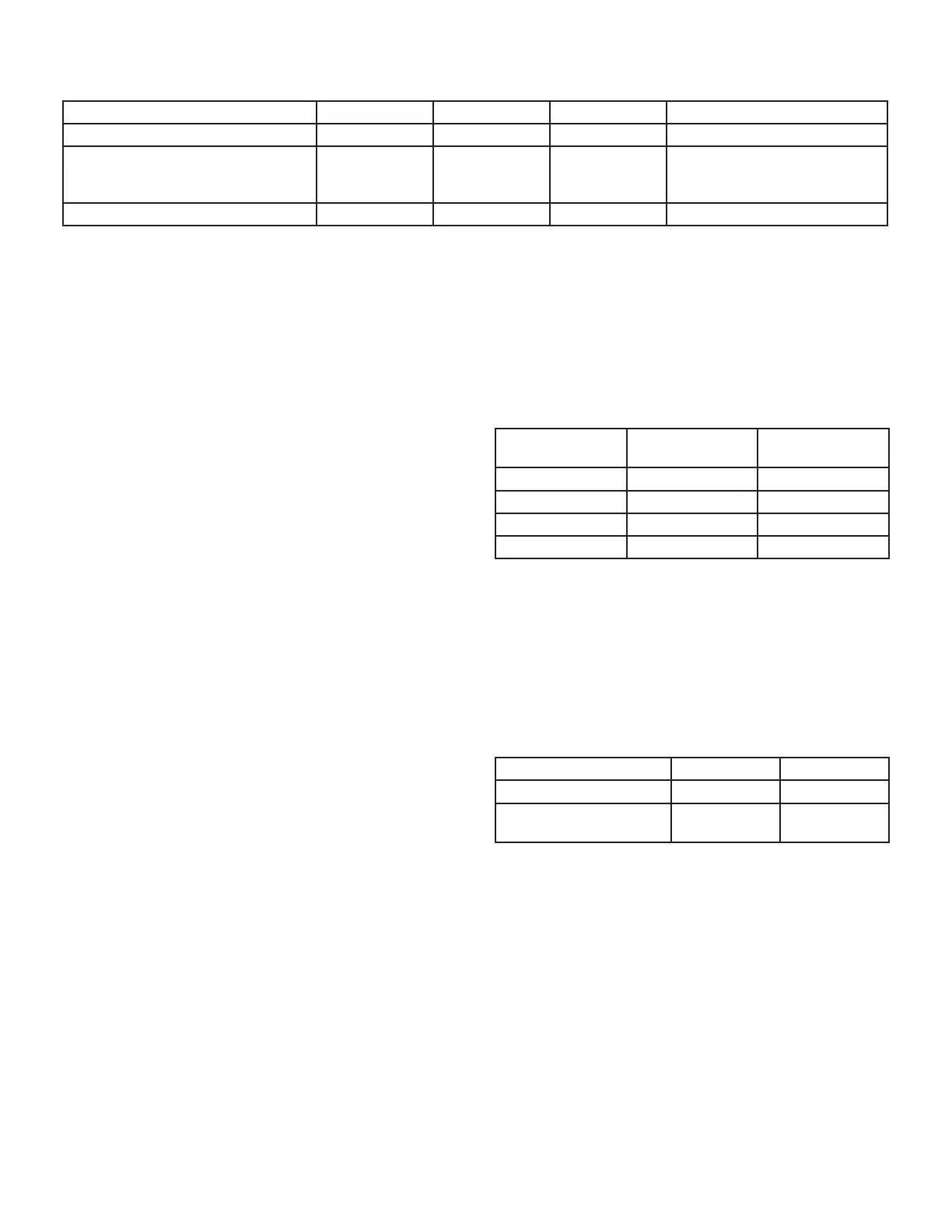
TABLE 16
Non-Communicating Thermostat Selection Switch Settings
Operation Thermostat Switch 1 Switch 2 Switch 3
Variable Capacity Heat (35% to 100%) Two-Stage O On O
Three-Stage Heat
(35%, 70%, 100%)
Single-Stage On O
2nd stage delay OFF = 7 minutes
ON = 12 minutes 3rd stage delay
10 minutes xed
Two-Stage Heat (W1 70%, W2 100%) Two-Stage O O O
NOTE - When the SLP99DFV is used with a communi-
cating thermostat, all indoor blower speed selections and
DIP switch settings are made by the communicating ther-
mostat.
SLP99DFV units are equipped with an integrated con-
trol. This control manages ignition timing, combustion air
inducer speed, heating mode fan o delays and indoor
blower speeds based on selections made using the con-
trol DIP switches and on-board links. The control includes
an internal Watchguard feature which automatically resets
the ignition control when it has been locked out.
NOTE - All DIP switches are factory shipped in the “OFF”
position.
Heating Operation DIP Switch Settings -- Figure 47
Switch 1 -- Thermostat Selection -- This unit may be
used with either a single-stage or two-stage thermostat.\
The thermostat selection is made using a DIP switch
which must be properly positioned for the particular appli-
cation. The DIP switch is factory-positioned for use with a
twostage thermostat. If a single-stage thermostat is to be
used, the DIP switch must be repositioned. See TABLE
16.
Switch 2 -- Operating Mode with Two-Stage Ther-
mostat -- If a two-stage thermostat is used, the furnace
can operate in either variable-capacity or conventional
twostage mode. When variable-capacity mode is select-
ed, the ring rate of the unit is varied to maximize comfort.
Conventional two-stage mode is the factory default set-
ting. See TABLE 16.
Switch 3 -- Second-Stage Heat On Delay -- If a single-
stage thermostat is used, the integrated control can be
used to energize second-stage heat after either 7 minutes
or 12 minutes of rst-stage heat operation. See TABLE 16.
Switches 4 and 5 -- Blower-O Delay -- The blower-on
delay of 45 seconds is not adjustable.The blower-o delay
(time that the blower operates after the heating demand
has been satised) can be adjusted by moving switches 4
and 5 on the integrated control. The unit is shipped from
the factory with a blower-o delay of 120 seconds
The blower o delay aects comfort and is adjustable
to satisfy individual applications. Adjust the blower o
delay to achieve a supply air temperature between 90°
and 110°F at the exact moment that the blower is de-en-
ergized. Longer o delay settings provide lower supply air
temperatures; shorter settings provide higher supply air
temperatures. TABLE 17 provides the blower o timings
that will result from dierent switch settings.
TABLE 17
Blower-O Delay Switch Settings
Blower-O Delay
(Seconds)
Switch 4
Switch 5
90 O On
120 (factory) O O
180 On O
210 On On
Indoor Blower Operation DIP Switch Settings
Switches 6 and 7 -- Continuous Indoor Fan Opera-
tionBlower Speed -- The unit is shipped from the factory
with the DIP switches positioned for medium low (2) speed
during continuous indoor blower operation. The table be-
low provides the continuous blower speeds that will result
from dierent switch settings. Refer to “BLOWER DATA”
on page 45 for corresponding cfm values.
TABLE 18
Continuous Indoor Blower Operation -- Blower Speeds
Speed Switch 6 Switch 7
1 - Low (28%)* O On
2 - Medium Low (38%)*
Factory
O O
* Percentage of high speed cooling

 Loading...