EasyManua.ls Logo

Lennox SLP99DFV Series User Manual

Lennox SLP99DFV Series
75 pages
To Next Page IconTo Next Page
Page #1 background imageLoading...
Page #1 background image
Page 1
UNIT INFORMATIONUNIT INFORMATION
Service Literature
©2016 Lennox Industries, Inc.
WARNING
Improper installation, adjustment, alteration, service
or maintenance can cause property damage, personal
injury or loss of life. Installation and service must be
performed by a licensed professional HVAC installer or
equivalent, service agency, or the gas supplier.
CAUTION
As with any mechanical equipment, contact with sharp
sheet metal edges can result in personal injury. Take
care while handling this equipment and wear gloves and
protective clothing.
WARNING
Electric shock hazard. Can cause injury or
death. Before attempting to perform any
service or maintenance, turn the electrical
power to unit OFF at disconnect switch(es).
Unit may have multiple power supplies.
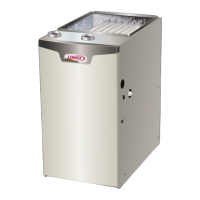
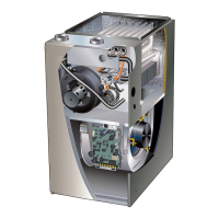
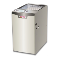
SLP99DFV series units are high-e󰀩ciency downow gas
furnaces equipped with variable capacity gas valve, vari-
able speed combustion air inducer and variable speed
indoor blower motor. All models are designed for direct
vent (dual pipe) venting system only. SLP99DFV units are
available in heating capacities from 66,000 to 132,000
Btuh (19.3 to 38.6 kW) and cooling applications from 2 to
5 tons (7.0 kW to 17.5 kW). Refer to Engineering Hand-
book for proper sizing.
Units are factory-equipped for use with natural gas. Kits
are available for conversion to LP operation. SLP99DFV
models include a SureLight
®
variable integrated control
that can be used with a communication thermostat as part
of a communicating comfort system. All SLP99DFV units
meet the California Nitrogen Oxides (NOx) Standards and
California Seasonal E󰀩ciency requirements.
All specications in this manual are subject to change.
Procedures outlined in this manual are presented as rec-
ommendations only and do not supersede or replace local
or state codes. In the absence of local or state codes, the
guidelines and procedures outlined in this manual (except
where noted) are recommendations only and do not con-
stitute code.
TABLE OF CONTENTS
Specications . . . . . . . . . . . . . . . . . . . . . . . . . . . . . Page 2
Optional Accessories . . . . . . . . . . . . . . . . . . . . . . Page 3
Blower Data . . . . . . . . . . . . . . . . . . . . . . . . . . . . . . Page 4
I Unit Components . . . . . . . . . . . . . . . . . . . . . . . Page 10
II Communicating Thermostat . . . . . . . . . . . . . . Page 36
III Placement and Installation . . . . . . . . . . . . . . Page 39
IV Start Up . . . . . . . . . . . . . . . . . . . . . . . . . . . . . . Page 55
V Heating System Service Checks . . . . . . . . . . Page 56
VI Typical Operating Characteristics . . . . . . . . Page 62
VII Maintenance . . . . . . . . . . . . . . . . . . . . . . . . . . Page 62
VIII Wiring and Sequence of Operation . . . . . Page 65
IX Field Wiring . . . . . . . . . . . . . . . . . . . . . . . . . . . Page 73
SLP99DFV
100002
10/2021
SLP99DFV SERIES UNITS

Other manuals for Lennox SLP99DFV Series

Question and Answer IconNeed help?

Do you have a question about the Lennox SLP99DFV Series and is the answer not in the manual?

Lennox SLP99DFV Series Specifications

General IconGeneral
BrandLennox
ModelSLP99DFV Series
CategoryFurnace
LanguageEnglish

Summary

SLP99DFV SERIES UNITS

Specifications

Detailed technical specifications for the SLP99DFV units, including performance data.

Optional Accessories

List of optional accessories available for order, such as kits and controls.

BLOWER DATA

HEATING BLOWER PERFORMANCE

Airflow data for heating operation at various static pressures and speed settings.

COOLING BLOWER PERFORMANCE

Airflow data for cooling operation at various static pressures and speed settings.

I-UNIT COMPONENTS

A-Control Box

Detailed description of the components within the furnace's control box.

ELECTROSTATIC DISCHARGE (ESD) Precautions and Procedures

Safety guidelines for handling electronic components to prevent electrostatic discharge damage.

Electronic Ignition

Thermostat Selection Modes

How to configure the furnace operation based on thermostat type using DIP switches.

Variable Capacity

Description of the variable capacity heating mode operation.

Three-Stage Timed Operation

Description of the three-stage timed heating mode operation.

INTEGRATED CONTROL CONFIGURATION GUIDE

THERMOSTAT SELECTION

Guide to selecting the appropriate thermostat settings and DIP switches for furnace operation.

HEATING BLOWER-OFF DELAY

Configuration options for the blower's off delay time during heating cycles.

Heating Operation DIP Switch Settings

Switch 1 -- Thermostat Selection

DIP switch setting to select between single-stage and two-stage thermostat operation.

Switch 2 -- Operating Mode with Two-Stage Thermostat

DIP switch setting to select variable or conventional two-stage mode.

Switch 3 -- Second-Stage Heat On Delay

DIP switch setting to adjust the delay for second-stage heat activation.

Cooling Mode Blower Speed Adjustment

Switches 10 and 11 -- Cooling Mode Blower Speed Adjustment

DIP switch settings to adjust cooling blower speed by +/- 10%.

Switches 12 and 13 -- Cooling Mode Blower Speed Ramping

DIP switch settings for selecting cooling mode blower speed ramping profiles.

Heating Mode Blower Speed

Switches 14 through19 -- Heating Mode Blower Speed

DIP switch settings to select heating mode blower speeds for low and high heat.

Diagnostic LED (FIGURE 4)

Error Code Recall Mode

Procedure to access and clear diagnostic error codes displayed by the LED.

Field Test Mode

Mode for testing furnace functions, including ignition and pressure switch calibration.

Configuring Unit Size Codes

LED 7 Segment Status / Error Code

Integrated Control Diagnostic Codes (Continued)

OPERATING SEQUENCE

B-Blower Compartment (FIGURE 7)

Internal Operation

Explanation of how the ECM motor operates via serial communication with the integrated control.

1. Blower Motor (B3)

Description of the blower motor, its types, and basic operation.

Motor Start-Up

Troubleshooting Motor Operation (FIGURE 10)

Troubleshooting Motor Windings

TEST A

Procedure to test motor winding resistance to ground for continuity.

TEST B

Procedure to test motor phase-to-phase winding resistance.

C-Heating Components (FIGURE 14)

1. Ignitor

Description of the silicon nitride ignitor and its voltage requirements for ignition.

2. Flame Sensor

Location and function of the flame sensor for monitoring burner operation.

3. Flame Rollout Switches

Description of the high-temperature limit switches that protect against flame rollout.

6. Primary Limit Control (S10)

7. Gas Valve (GV1)

8. Combustion Air Inducer (B6) & Pressure Switch (S18)

Vent Calibration

Procedure for calibrating the vent system parameters for proper furnace operation.

Measuring pressure differential FIGURE 18

Measuring Pressure Differential

Pressure Switch 0' to 7500'

Table specifying pressure switch set points for high and low fire.

Combustion Air Inducer / Cold End Header Box / Vent Pipe Assembly

II-Communicating Thermostat (if applicable)

Communicating Enabled Furnace and Non-Communicating Outdoor Unit

Wiring diagram for a communicating system with a non-communicating outdoor unit.

Communicating Enabled Furnace and Communicating Enabled Outdoor Unit

Wiring diagram for a communicating system with a communicating outdoor unit.

Optional Accessories for use with any Communicating System

Wiring Diagram

Wiring details for optional accessories like HEPA filters and LVCS ventilation controls.

III-PLACEMENT AND INSTALLATION

PIPING AND FITTINGS SPECIFICATIONS

Specifications for approved PVC, CPVC, and ABS piping and fittings materials.

UL 1738 CERTIFIED GAS VENTING SYSTEM

Approved UL 1738 certified gas venting system components.

Joint Cementing Procedure

Venting Practices

Exhaust Piping (FIGURE 25 and FIGURE 27)

Instructions and diagrams for routing and installing exhaust piping.

Vent Piping Guidelines

General guidelines and approved materials for vent piping installation.

Maximum Allowable Intake or Exhaust Vent Length in Feet

VENT TERMINATION CLEARANCES FOR DIRECT VENT INSTALLATIONS IN THE USA AND CANADA

Clearance above grade, veranda, porch, deck or balcony

Required clearances from grade, porches, decks, and balconies for vent terminals.

Clearance to window or door that may be opened

Required clearances from operable windows and doors for vent terminals.

General Guidelines for Vent Terminations

Maximum Allowable Vent Pipe Length (in ft.)³ Without Insulation In Unconditioned Space

Table for maximum allowable vent pipe length without insulation in unconditioned spaces.

Details of Intake and Exhaust Piping Terminations for Direct Vent Installations

EXHAUST PIPE TERMINATION SIZE REDUCTION

Table indicating required exhaust pipe size reductions for specific termination types.

Condensate Piping

CONDENSATE TRAP AND PLUG LOCATIONS

Diagrams showing locations for condensate trap and plug connections.

IV-START-UP

B-Heating Start-Up

Step-by-step instructions for initiating heating operation and priming the condensate trap.

Gas Valve Operation (FIGURE 47)

Failure To Operate

V-HEATING SYSTEM SERVICE CHECKS

C-Testing Gas Piping

Procedures for testing gas piping connections for leaks and proper pressure.

E-Testing Gas Supply Pressure

Manifold Pressure Measurement (FIGURE 49)

G- Proper Combustion

High Fire

Combustion analysis specifications for high fire operation (CO2%).

Low Fire

Combustion analysis specifications for low fire operation (CO2%).

H- High Altitude

Conversion Kit Requirements

Table detailing conversion kit requirements for high altitude installations.

I- Proper Ground and Voltage

Voltage Checks

Procedures for measuring AC voltage at various points on the integrated control.

J-Discharge Air Temperature Sensor (DATS)

Discharge Air Temperature Sensor Wiring

Diagram illustrating the wiring connections for the discharge air temperature sensor.

VII-MAINTENANCE

Filters

Guidance on inspecting, cleaning, or replacing the furnace filters.

Exhaust and air intake pipes

Cleaning Heat Exchanger

Cleaning the Burner Assembly

VIII- Wiring and Sequence of Operation

Two-Stage Thermostat Heating Sequences

Description of heating sequences when using a two-stage thermostat.

Single-Stage Thermostat Heating Sequences

A - Sequence of Operation and Troubleshooting Flow Chart

IGNITION AND CALL FOR LOW FIRE WITH TWO-STAGE THERMOSTAT

Flow chart detailing ignition and low fire call sequence with a two-stage thermostat.

CALL FOR HIGH FIRE WITH TWO-STAGE THERMOSTAT

IGNITION AND CALL FOR HEAT WITH SINGLE-STAGE THERMOSTAT

CALL FOR COOLING

IX- Field Wiring For Non-Communicating Thermostats

1Heat / 1 Cool

Wiring configuration for 1 heat / 1 cool system with non-communicating thermostats.

1 Heat / 2 Cool

Wiring configuration for 1 heat / 2 cool system with non-communicating thermostats.

DIP Switch Settings and On-Board Links

2 Heat / 2 Cool

Wiring configuration for 2 heat / 2 cool system with non-communicating thermostats.

2 Heat / 1 Cool

Wiring configuration for 2 heat / 1 cool system with non-communicating thermostats.

DIP Switch Settings and On-Board Links

Dual Fuel Single-Stage Heat Pump

Wiring configuration for dual fuel single-stage heat pump systems.

Dual Fuel Two Stage Heat Pump

Wiring configuration for dual fuel two-stage heat pump systems.
Related product manuals