Page 14
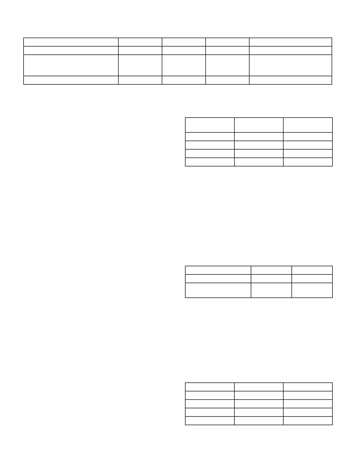
TABLE 3
Thermostat Selection Switch Settings
Operation Thermostat Switch 1 Switch 2 Switch 3
Variable Capacity Heat (35% to 100%) Two-Stage O On O
Three-Stage Heat
(35%, 70%, 100%)
Single-Stage On O
2nd stage delay OFF = 7 minutes
ON = 12 minutes 3rd stage delay
10 minutes xed
Two-Stage Heat (W1 70%, W2 100%) Two-Stage O O O
NOTE - When the SLP99DFV is used with a communicat-
ing thermostat, all indoor blower speed selections and DIP
switch settings are made by the thermostat.
NOTE - All DIP switches are factory shipped in the “OFF”
position.
Heating Operation DIP Switch Settings -- FIGURE 4
Switch 1 -- Thermostat Selection -- This unit may be
used with either a single-stage or two-stage thermostat.
The thermostat selection is made using a DIP switch
which must be properly positioned for the particular appli-
cation. The DIP switch is factory-positioned for use with a
twostage thermostat. If a single-stage thermostat is to be
used, the DIP switch must be repositioned. See TABLE 3.
Switch 2 -- Operating Mode with Two-Stage Ther-
mostat -- If a two-stage thermostat is used, the furnace
can operate in either variable-capacity or conventional
twostage mode. When variable-capacity mode is select-
ed, the ring rate of the unit is varied to maximize comfort.
Conventional two-stage mode is the factory default set-
ting. See TABLE 3.
Switch 3 -- Second-Stage Heat On Delay -- If a single-
stage thermostat is used, the integrated control can be
used to energize second-stage heat after either 7 minutes
or 12 minutes of rst-stage heat operation. See TABLE 3.
Switches 4 and 5 -- Blower-O Delay -- The blower-on
delay of 45 seconds is not adjustable. The blower-o delay
(time that the blower operates after the heating demand
has been satised) can be adjusted by moving switches 4
and 5 on the integrated control. The unit is shipped from
the factory with a blower-o delay of 120 seconds. The
blower o delay aects comfort and is adjustable to sat-
isfy individual applications. Adjust the blower o delay to
achieve a supply air temperature between 90° and 110°F
at the exact moment that the blower is de-energized. Lon-
ger o delay settings provide lower supply air tempera-
tures; shorter settings provide higher supply air tempera-
tures. TABLE 4 provides the blower-o timings that will
result from dierent switch settings.
TABLE 4
Blower-O Delay Switch Settings
Blower-O Delay
(Seconds)
Switch 4
Switch 5
90 O On
120 (factory) O O
180 On O
210 On On
Indoor Blower Operation DIP Switch Settings
Switches 6 and 7 -- Continuous Indoor Fan Operation --
Blower Speed - Switches 6 and 7 are used to select blow-
er motor speeds during continuous indoor blower opera-
tion. The unit is shipped from the factory with DIP switches
positioned for medium low (2) speed during continuous
indoor blower operation. TABLE 5 provides the continuous
blower speeds that will result from various switch settings.
Refer to blower tables at the front of this manual for corre-
sponding cfm values.
TABLE 5
Continuous Indoor Blower Operation -- Blower Speeds
Speed Switch 6 Switch 7
1 - Low (28%)* O On
2 - Medium Low (38%)*
Factory
O O
Switches 8 and 9 -- Cooling Mode Blower Speed --
Switches 8 and 9 are used to select cooling blower motor
speed. The unit is shipped from the factory with the DIP
switches positioned for high speed (4) indoor blower mo-
tor operation during the cooling mode. TABLE 6 provides
the cooling mode blower speeds that will result from dier-
ent switch settings. Refer to blower tables at the front of
this manual for corresponding cfm values.
TABLE 6
Cooling Mode Blower Speeds
Speed Switch 8 Switch 9
1 - Low On On
2 - Medium Low O On
3 - Medium High On O
4 - High Factory O O

 Loading...


