Page 32
8. Combustion Air Inducer (B6) & Pressure Switch
(S18)
All SLP99UHV units are equipped with a combustion air
inducer (B6) and dual pressure switch assembly (high re
and low re). The pressure switch (FIGURE 17) serves
four functions. First it establishes calibration points for
the vent calibration routine. The combustion air inducer’s
speed at a given ring rate is a function of the vent system
resistance. The calibration routine establishes the inducer
speed required to make low and high re switches for a
given vent pipe installation and interpolates the speeds
required to achieve all intermediate rates between these
two points. The setting for lowre switch on the assembly
is such that it does not normally enter into the vent cali-
bration routine.
Second, the switch proves combustion air inducer oper-
ation by sensing a vacuum energizing the control circuit
and allowing ignition. The low re pressure switch pro-
vides this function.
Third, the switch interrupts the combustion process in the
event vent outlet or combustion air intake blockage. Final-
ly, the switch interrupts the combustion process if the con-
densate drainage system becomes blocked to the point
the condensate level builds up in the cold end header box/
secondary coil or vent system.
If the switch assembly is to be replaced, replace the en-
tire assembly. Individual switch components cannot be
replaced.
Combustion Air Inducer Specications
• Three phase AC induction motor
• Sealed ball bearings
• VFD controlled by the furnace control board
• Operates at 60 to 180Hz
• Voltage range 33 - 110 VAC
• Amp draw 0.75 - 1.0
• Windings resistance 16.74 / 14.26
• Speed range 1000 - 5400 RPM
Combustion Air Inducer Troubleshooting
• Is the CAI mounted correctly?
• Any air or condensate leaks?
• Does the motor and wheel turn freely?
• Any missing or broken mounting screws?
• Perform a visual inspection
• Clean as needed
• Measure the resistance between each of the wind-
ings. All readings should read 16.74 / 14.26 and be
approximately 10% of each other.
• Check each winding to ground to conrm there is
no continuity / not grounded
WARNING
The pressure switch is a safety shut-down control
in the furnace and must not be jumpered for any
reason other than troubleshooting.
Pressure Switch Troubleshooting
To troubleshoot the pressure switch, add a temporary
jumper. The unit will not re with the switch jumpered.
Therefore, the pressure switch must be bypassed after
the combustion air inducer is activated. This will determine
if the pressure switch and furnace are operating properly.
However, this may not indicate if the sealed combustion
system is operating properly.
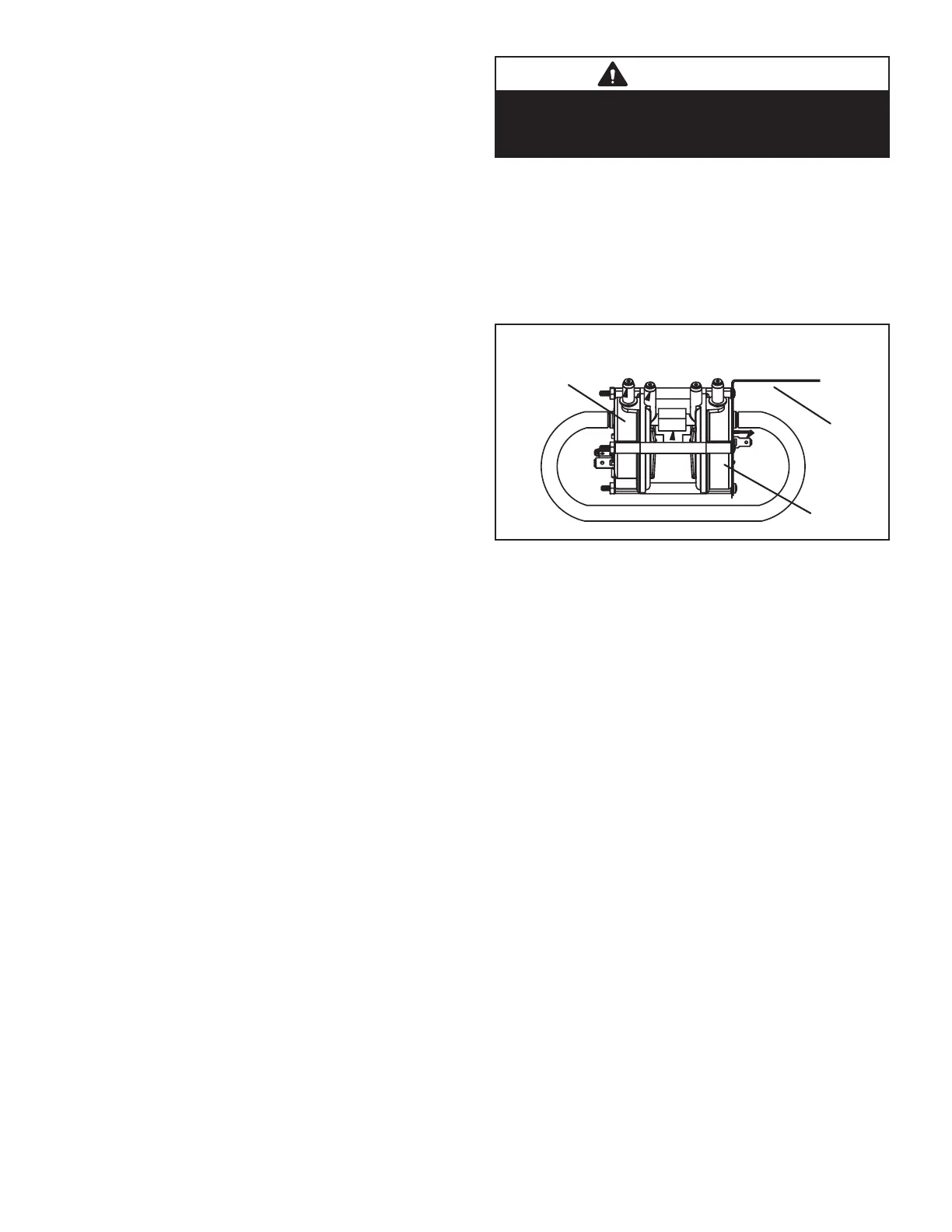
bracket
low fire
high fire
Pressure Switch (S18)
FIGURE 17
Vent Calibration
The vent calibration sequence establishes furnace oper-
ating parameters in a specic installation. The integrat-
ed control runs the calibration and may be repeated as
necessary to maintain proper furnace operation. Prior to
calibration, all duct work (and returns) vent pipe and con-
densate trap (primed) must be connected.
If calibration is successful the data is stored in memory
and will be used to determine furnace operation and main-
tain parameters during heat call. If calibration is not suc-
cessful, the integrated control will proceed to a 5 minute
delay and signal the appropriate code. After the 5 minute
delay the calibration will be repeated 4 more times with a
5 minute delay in between. If still unsuccessful after the
4 trials (total 5) the integrated control will go into a 1 hour
soft lockout.
Calibration may be initiated by:
• Initial call for heat
• Cycling main power o / on and then call for heat
• Venting conditions change (aecting high and low
pressure switch operation)
• Ramp down low re switch check failed (calibration
will follow next call for heat)
• The service technician (by pressing the push but-
ton found on the integrated control until the control
cycles through to “Field Test Mode”)

 Loading...


