Page 27
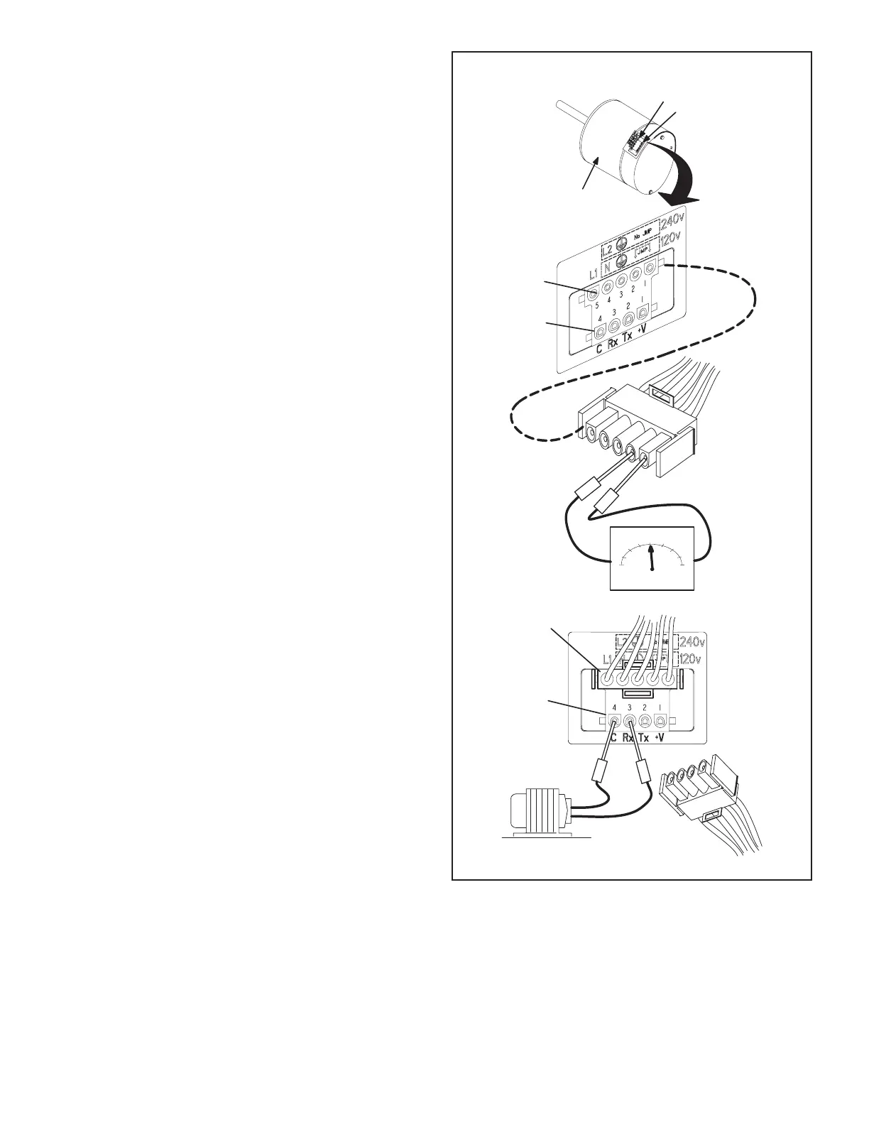
Troubleshooting Motor Operation (FIGURE 10)
To verify motor operation see steps below:
1 - Remove J48 (5 pin power plug) from P48 on the
motor.
2 - With the power on at the furnace and door switch
depressed, use a test meter to verify 120V between
pins 4 and 5 on J48.
3 - Reconnect J48 to P48 on the motor.
4 - Remove J49 (4 pin low voltage connector) from P49
on the motor.
5 - Using test jumpers, apply 24V to pins 3 and 4 on
P49on the motor.
Note: Do not apply 24V to pins 2 and 4 on P49.
Doing so will cause permanent damage to the motor.
6 - Motor should run at 75%.
7 - Test is complete. Remove jumpers and reconnect
plugs.
Another option is to use the TECMate PRO motor tester
with the 16 to 4 pin adaptor. The use of the TECMate PRO
isolates the motor from the integrated control. Follow the
instructions provided with the kit. If the motor runs do not
replace.
BLOWER B3 HARNESS CONNECTORS
MOTOR with INTEGRATED
CONTROLLER
SHAFT
P49 4 Pin
P48 5 Pin
P48 5 Pin
P49 4 Pin
J48 Connector
installed on motor
P49 4 Pin
120v
0
240v
5
4
3
2
1
J48 Connector
24v Transformer
J49 Connector
FIGURE 10

 Loading...


