Page 61
J-Discharge Air Temperature Sensor (DATS)
Units may have a discharge air temperature sensor locat-
ed in the supply duct or in the coil. Two type sensors are
used. FIGURE 52 (located in the coil) and FIGURE 54
(located in the plenum). If the sensor is suspect, check
the location using TABLE 35 and FIGURE 53 (type 1) or
TABLE 36 and FIGURE 55 (type 2). See FIGURE 56 for
eld wiring to the furnace control. If the location and wiring
are correct, but the sensor is not working properly, replace
the sensor. Follow the DATS instructions found in the kit
for replacing the sensor. The location is not compatible
between sensor types.
FIGURE 52
TABLE 35
Sensor Type 1
Unit “a” “b”
070V36B 3” from bottom 2-1/2” from right
090V36C 4-1/2” from bottom 3-1/2” from right
090V48C 6” from bottom 4-1/2” from right
090V60C 6” from bottom 4” from right
110V60C 6” from bottom 3-1/2” from right
Discharge Air Temperature Sensor Coil Location
Coil
AIR FLOW
a
b
FIGURE 53
FIGURE 54
TABLE 36
Sensor Type 2
Unit “a” “b”
070V36B
6” center
090V36C
090V48C
090V60C
110V60C
Discharge Air Temperature Sensor Duct Location
Coil
AIR FLOW
a
b
Plenum
FIGURE 55
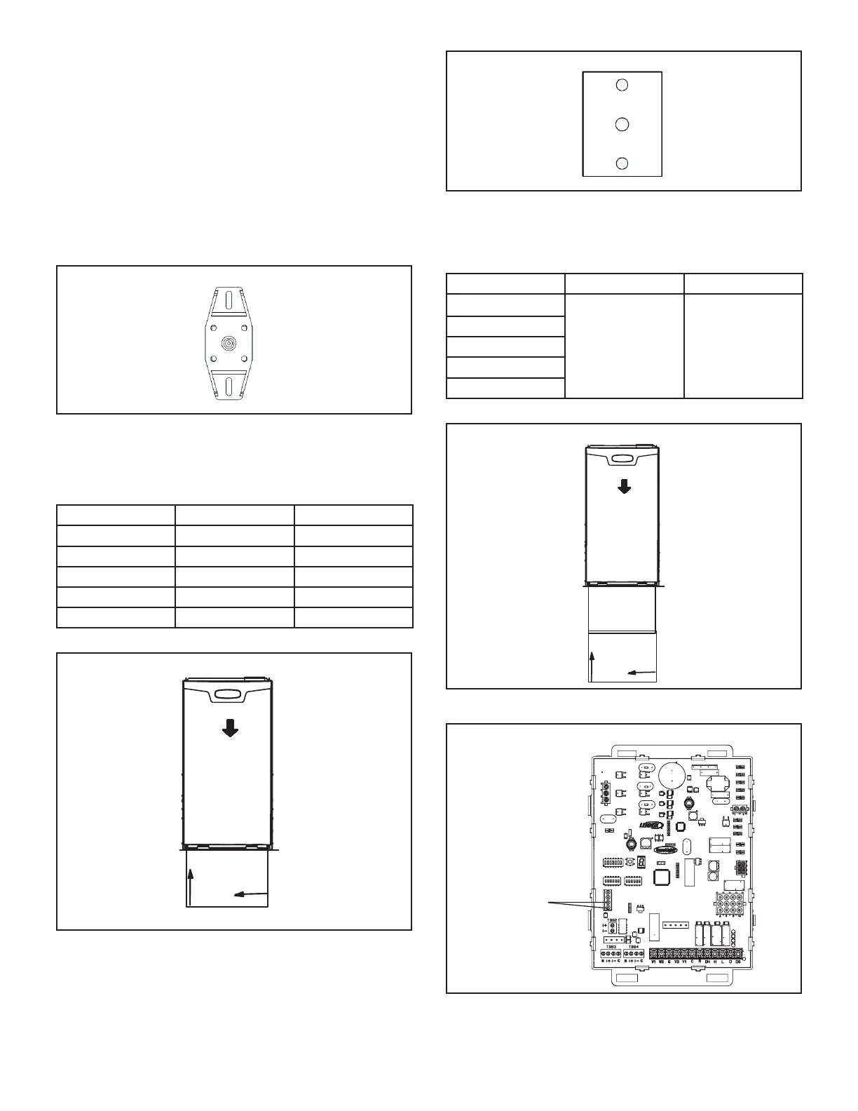
Discharge Air Temperature Sensor Wiring
+
DISCHARGE AIR
SENSOR
TERMINALS
W915
W951
W914
EAC
HUM
FIGURE 56

 Loading...


