Page 25
B-Blower Compartment (FIGURE 7)
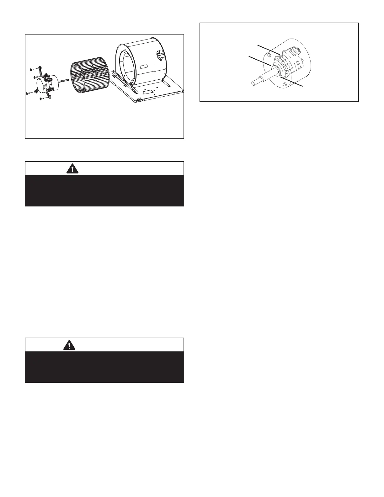
To Remove Blower From Unit:
1. Disconnect Power, 2. Remove access panels. 3. Remove
Control Box 4. Remove Bolts. 5. Unplug Motor Wires From
Control Board (070 unit remove exhaust and air intake pipe)
Then Slide Out Front of Unit.
FIGURE 7
1. Blower Motor (B3)
WARNING
During blower operation, the ECM motor emits
energy that may interfere with pacemaker operation.
Interference is reduced by both the sheet metal
cabinet and distance.
The SLP99DFV line uses three dierent motor sizes; 1/2
hp, 3/4 hp and 1hp. The motor communicates with the in-
tegrated control via a 2-way serial connection. The motor
receives all necessary functional parameters from the inte-
grated control and does not rely on a factory program like
traditional variable speed motors. SLP99UHV units use a
three-phase, electronically controlled D.C. brushless mo-
tor (controller converts single phase a.c. to three phase
D.C.), with a permanentmagnet- type rotor (FIGURE 8).
Because this motor has a permanent magnet rotor it does
not need brushes like conventional D.C. motors.
Internal components are shown in FIGURE 8. The stator
windings are split into three poles which are electrically
connected to the controller. This arrangement allows mo-
tor windings to turn on and o in sequence by the control-
ler.
IMPORANT
During blower operation, the ECM motor emits
energy that may interfere with pacemaker operation.
Interference is reduced by both the sheet metal
cabinet and distance.
STATOR
(WINDINGS)
BEARING
FIGURE 8
A solid-state controller is permanently attached to the mo-
tor. The controller is primarily an A.C. to D.C. converter.
Converted D.C. power is used to drive the motor. The con-
troller contains a microprocessor which monitors varying
conditions inside the motor (such as motor workload).
The controller uses sensing devices to sense what posi-
tion the rotor is in at any given time. By sensing the posi-
tion of the rotor and then switching the motor windings on
and o in sequence, the rotor shaft turns the blower.
All SLP99DFV blower motors use single phase power. An
external run capacitor is not used. The motor uses perma-
nently lubricated ball-type bearings.
Internal Operation
The motor is controlled via serial communication between
the integrated control on the furnace and the controller
attached to the motor shell. The messages sent back and
forth between the two controls serve to communicate rota-
tional direction, demand, motor size, current draw, torque,
and rpm, among other variables.
Motor rpm is continually adjusted internally to maintain
constant static pressure against the blower wheel. The
controller monitors the static work load on the motor and
motor amp-draw to determine the amount of rpm adjust-
ment. Blower rpm may be adjusted any amount in order to
maintain a constant cfm as shown in Blower Ratings Ta-
bles. The cfm remains relatively stable over a broad range
of static pressure. Since the blower constantly adjusts rpm
to maintain a specied cfm, motor rpm is not rated. Hence,
the terms “cool speed”, “heat speed ” or “speed tap” in
this manual, on the unit wiring diagram and on blower B3,
refer to blower cfm regardless of motor rpm.
Initial Power Up
When line voltage is applied to B3, there will be a large
inrush of power lasting less than 1/4 second. This inrush
charges a bank of DC lter capacitors inside the controller.
If the disconnect switch is bounced when the disconnect is
closed, the disconnect contacts may become welded. Try
not to bounce the disconnect switch when applying power
to the unit.

 Loading...


