Page 24
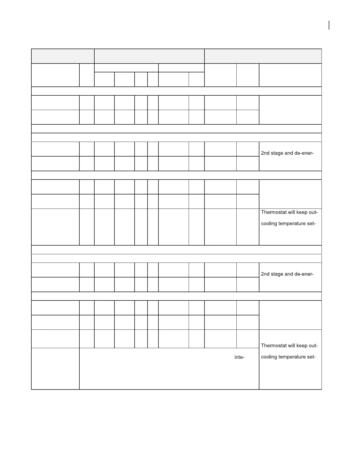
TABLE 16
OPERATING SEQUENCE
SLP99DFDV and Single-Stage Outdoor Unit
OPERATING
SEQUENCE
SYSTEM DEMAND SYSTEM RESPONSE
System
Condition
Step
Demand Relative Humidity
Compressor
Blower
CFM
(COOL)
Comments
1st
stage
2nd
stage
O
G
Status D*
NO CALL FOR DEHUMIDIFICATION
Normal Operation -
Y1
1 On On
On
Acceptable
24
VAC
Low 70%
Compressor and indoor
blower follow thermostat
demand
Normal Operation -
Y2
2 On
On
On
On
Acceptable
24
VAC
High 100%
ROOM THERMOSTAT CALLS FOR FIRST STAGE COOLING
BASIC MODE (only active on a Y1 thermostat demand)
Normal Operation 1 On On
On
Acceptable
24
VAC
Low 70%
Thermostat energizes
gizes D on a call for de-
humidification
Dehumidification
Call
2 On
On
On
On
Demand
0
VAC
High 70%
PRECISION MODE (operates independent of a Y1 thermostat demand)
Normal Operation 1 On On
On
Acceptable
24
VAC
Low 70%
Dehumidification mode
begins when humidity is
greater than set point
Dehumidification
call
2 On
On
On
On
Demand
0
VAC
High 70%
Dehumidification
call ONLY
1 On
On
On
On
Demand
0
VAC
High 70%
door unit energized after
point has been reached
in order to maintain room
humidity setpoint.*
ROOM THERMOSTAT CALLS FOR FIRST AND SECOND STAGE COOLING
BASIC MODE (only active on a Y1 thermostat demand)
Normal Operation 1 On
On
On
On
Acceptable
24
VAC
High 100%
Thermostat energizes
gizes D on a call for de-
humidification
Dehumidification
Call
2 On
On
On
On
Demand
0
VAC
High 70%
PRECISION MODE (operates independent of a Y1 thermostat demand)
Normal Operation 1 On On
On
Acceptable
24
VAC
Low 70%
Dehumidification mode
begins when humidity is
greater than set point
Dehumidification
call
2 On
On
On
On
Demand
0
VAC
High 70%
Dehumidification
call ONLY
1 On
On
On
On
Demand
0
VAC
High 70%
door unit energized after
point has been reached
in order to maintain room
humidity setpoint.
On-board links at indoor unit with a two-stage outdoor unit:
Cut factory link from Y1 to Y2 or cut W915 (Y1 to Y2) on SureLight
®
grated control.
With Condensing unit - Cut W914 (R to DS) on SureLight
®
integrated control;
With Heat Pump - Cut W914 (R to DS) & W951 (R to O) on SureLight
®
integrated control.
*CS
7500 thermostat only

 Loading...


