Page 11
Electronic Ignition
At the beginning of the heat cycle the SureLight
®
integrat-
ed control monitors the low re combustion air inducer
pressure switch. The control will not begin the heating cy-
cle if the low re pressure switch is closed (by-passed).
Likewise the control will not begin the high re heating
cycle if the high re pressure switch is closed, and will
remain in low re heat. However, if the high re pressure
switch closes during the low re heat pre-purge, the con-
trol will allow high re heat.
Once the low re pressure switch is determined to be
open, the combustion air inducer is energized on igni-
tion speed. When the dierential in the pressure switch is
great enough, the pressure switch closes and a 15-sec-
ond pre-purge begins. If the switch is not proven within
2-1/2 minutes, the inducer is de-energized and the control
will initiate vent calibration. If the vent calibration is unsuc-
cessful the control goes into a 5 minute delay. The control
will attempt vent calibration 3 more times before going into
a 1 hour soft lockout. After the 15 second pre-purge period
the SureLight ignitor warms up for 20 seconds.
The gas valve then opens for a 4-second trial for ignition.
The ignitor stays energized during this trial until ame is
sensed. If ignition is not proven during the 4-second trial
for ignition, the control will try four more times with an inter
purge and warm-up time between trials of 35 seconds. Af-
ter a total of ve trials for ignition (including the initial trial),
the control goes into Watchguard- Flame Failure mode.
After a 60-minute reset period, the control will begin the
ignition sequence again.
Thermostat Selection Modes
See table 3 for DIP switch settings
The control can be made to operate in three modes: vari-
able capacity, three-stage timed or two-stage. The vari-
able capacity and two-stage modes are only operational
with a two-stage thermostat. The thermostat selection is
made using DIP switches one and / or two (gure 4) and
must be positioned for the particular application.
Variable Capacity
Using a two-stage thermostat the system will operate in a
variable capacity sequence mode. In this mode, the con-
trol will vary the ring rate anywhere between 35% and
100% of full capacity. The indoor blower will be automat-
ically adjusted accordingly to provide the appropriate air-
ow at any rate. On the initial call for low re, the furnace
will operate at 35% and will remain there until the heat call
is satised or a call for high re is initiated. If there is a
call for high re the rate will increase by 10% if the current
rate is above 60%. However if the current rate is below
60% the rate will increase to 70%. After this initial rate
increase to 70% capacity, the furnace will increase rate by
10% every 5 minutes while a high re heat call is present.
If the high re heat call is satised but the low re heat call
is still present, the furnace will remain at the current ring
rate until the demand is satised or another call for high
re is initiated.
Three- Stage Timed Operation
Using a single-stage thermostat the system will operate
in a three stage timed mode. Upon a call for heat and a
successful ignition, the combustion air inducer will operate
at 35% and the indoor blower will adjust to the appropriate
cfm. After a eld selectable 7 or 12 minute delay period,
the inducer RPM will increase and the unit will operate at
70%. The indoor blower will adjust to the appropriate cfm.
After a factory set non-adjustable 10 minute delay expires
the furnace will increase rate to 100%. The indoor blower
will adjust to the appropriate cfm.
Two-Stage Operation
The system will also operate in conventional two-stage
mode. While in two-stage mode, the furnace will re on
low re (70% rate). The combustion air inducer will op-
erate at 70% and the indoor blower will adjust to the ap-
propriate cfm. The unit will switch to high re on a W2 call
from the thermostat. After a 30 second recognition period
(during which the integrated control will receive a contin-
uous W2 call) expires the furnace will increase to 100%
rate. The inducer will increase to 100% speed and the
indoor blower will adjust to appropriate cfm. If there is a
simultaneous call for rst and second stage heat, the unit
will re on rst stage heat and switch to second stage heat
after 30 seconds of operation.
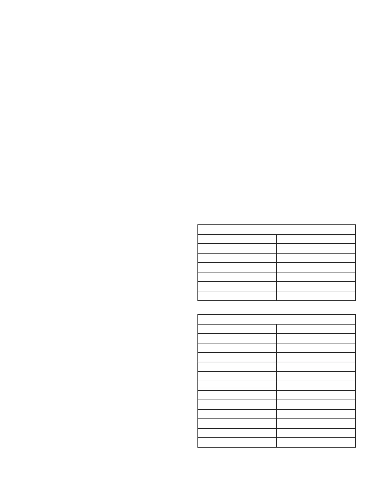
TABLE 1
SureLight
®
Control 6 Pin Terminal Designation
Pin # Function
1 Data Input From Motor
2 Common
3 Not Used
4 Data Output To Motor
5 5 Volt Bias Supply
6 Not Used
TABLE 2
SureLight Control 12 Pin Terminal Designation
Pin # Function
1 Not used
2 High Fire Pressure Switch
3 Rollout In
4 Ground
5 24V Hot
6 Primary Limit In
7 Gas Valve
8 Gas Valve Common
9 24V Neutral
10 Ground
11 Primary Limit Switch Out
12 Low Fire Pressure Switch

 Loading...


