Page 6
NOTWITHSTANDING THE FOREGOING, INSTALLER
IS RESPONSIBLE FOR CONFIRMING THAT THE USE
OF CONSTRUCTION HEAT IS CONSISTENT WITH THE
POLICIES AND CODES OF ALL REGULATING ENTI-
TIES. ALL SUCH POLICIES AND CODES MUST BE AD-
HERED TO.
General
CAUTION
SLP99DFV unit should not be installed in areas normally
subject to freezing temperatures.
These instructions are intended as a general guide and do
not supersede local codes in any way. Consult authorities
having jurisdiction before installation.
In addition to the requirements outlined previously, the
following general recommendations must be considered
when installing a SLP99DFV furnace:
• Place the furnace as close to the center of the air distri-
bution system as possible. The furnace should also be
located close to the chimney or vent termination point.
• When the furnace is installed in an attic or other insulat-
ed space, keep insulation away from the furnace.
• When the furnace is installed in an unconditioned
space, consider provisions required to prevent freezing
of condensate drain system.
Installation - Setting Equipment
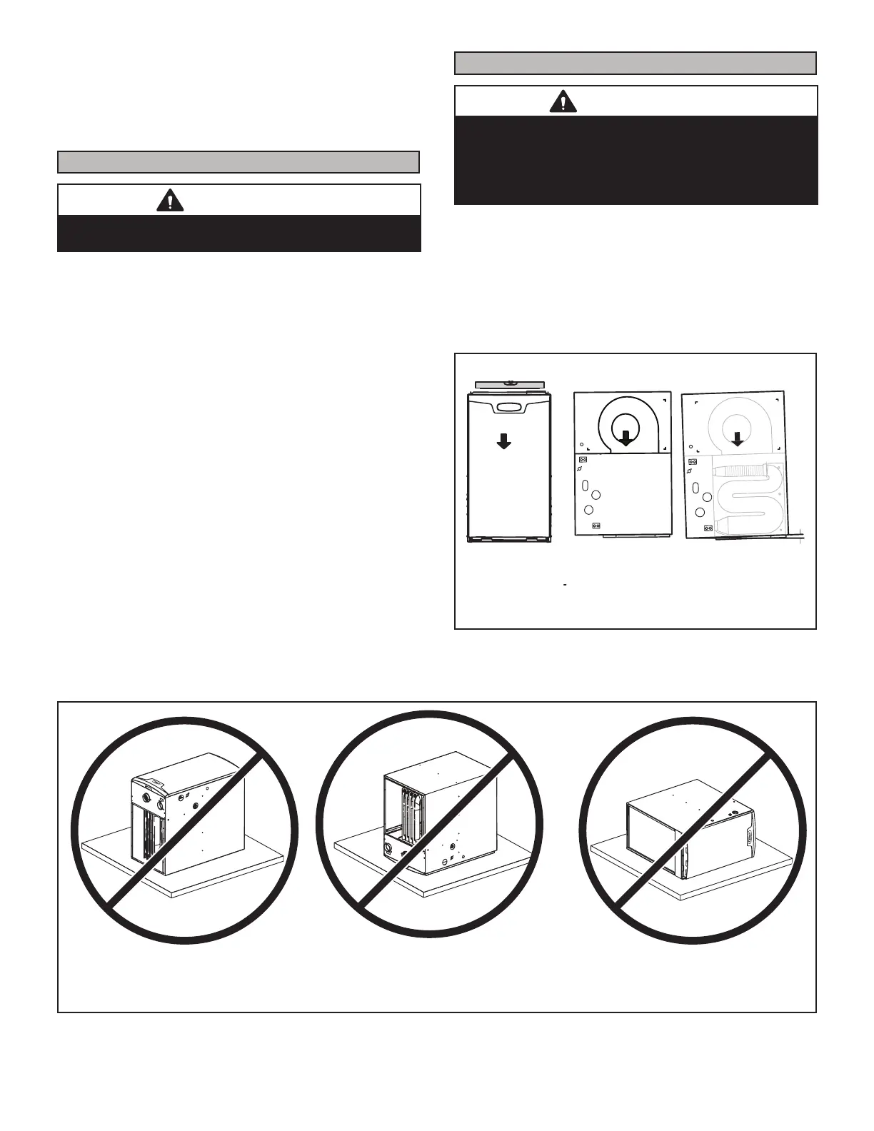
WARNING
Do not install the furnace on its front, back or in the
horizontal position. See FIGURE 5. Do not connect the
return air ducts to the back of the furnace. Doing so
will adversely aect the operation of the safety control
devices, which could result in personal injury or death.
Select a location that allows for the required clearances
that are listed on the unit nameplate. Also consider gas
supply connections, electrical supply, vent connection,
condensate trap and drain connections, and installation
and service clearances [24 inches (610 mm) at unit front].
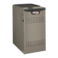
The unit must be level from side to side. Unit may be
positioned from level to 1/2” toward the front to aid in
draining. See FIGURE 4.
SETTING EQUIPMENT
FRONT VIEW SIDE VIEW
AIR FLOW
AIR FLOW
1/2”
AIR FLOW
SIDE VIEW
Unit must be level side-to-side. Unit may be positioned
from level to 1/2” toward the front to aid in draining.
FIGURE 4
Front
NOTE - Do not install the furnace on its front, back or in the horizontal position
Back
Horizontal
FIGURE 5

 Loading...