Page 1
UNIT INFORMATIONUNIT INFORMATION
Service Literature
©2016 Lennox Industries, Inc.
WARNING
Improper installation, adjustment, alteration,
service or maintenance can cause property damage,
personal injury or loss of life. Installation and service
must be performed by a licensed professional HVAC
installer (or equivalent), service agency or the gas
supplier.
WARNING
Shock hazard. Disconnect power before
servicing. Integrated control is not eld
repairable. If control is inoperable, simply
replace entire control. Can cause injury
or death. Unsafe operation will resul if
repair is attempted.
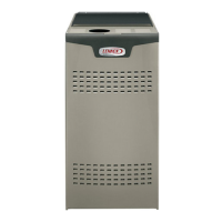
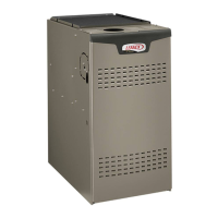
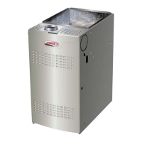
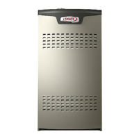
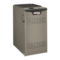
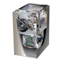
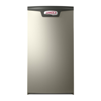
SL280DFV series units are 80% eciency gas furnaces
used for downow applications only, manufactured with
Lennox Duralok heat exchangers formed of aluminized
steel. Units are available in heating capacities of 66,000 to
110,000 Btuh and cooling applications up to 5 tons. Refer
to Engineering Handbook for proper sizing.
Units are factory equipped for use with natural gas. Kits
are available for conversion to LPG operation. SL280DFV
model units are equipped with a communicating enabled
SureLight
®
two-stage variable speed integrated control.
All units use a redundant gas valve to assure safety shut-
o as required by CSA.
All specications in this manual are subject to change.
Procedures outlined in this manual are presented as a
recommendation only and do not supersede or replace lo-
cal or state codes. In the absence of local or state codes,
the guidelines and procedures outlined in this manual (ex-
cept where noted) are recommendations only and do not
constitute code.
CAUTION
As with any mechanical equipment, contact with
sharp sheet metal edges can result in personal
injury. Take care while handling this equipment and
wear gloves and protective clothing.
TABLE OF CONTENTS
Specications . . . . . . . . . . . . . . . . . . . . . . . . . . . . . Page 2
Parts Identication . . . . . . . . . . . . . . . . . . . . . . . . . Page 7
I Unit Components . . . . . . . . . . . . . . . . . . . . . . . . Page 8
II Installation . . . . . . . . . . . . . . . . . . . . . . . . . . . . Page 36
III Start Up . . . . . . . . . . . . . . . . . . . . . . . . . . . . . . Page 36
IV Heating System Service Checks . . . . . . . . . Page 38
V Typical Operating Characteristics . . . . . . . . . Page 41
VI Maintenance . . . . . . . . . . . . . . . . . . . . . . . . . . Page 41
VII Wiring and Sequence of Operation . . . . . . Page 44
VIII Program Unit Capacity Size Mode . . . . . . Page 61
IX Field Wiring and Jumper Settings . . . . . . . . Page 47
X Troubleshooting Flow Chart . . . . . . . . . . . . . . Page 62
SL280DFV
Corp 1117-L4
Revised 03/2022
COMMUNICATING ENABLED SL280DFV SERIES UNITS



 Loading...