EasyManua.ls Logo

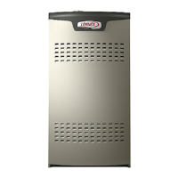
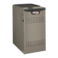
Lennox SL280V User Manual

Lennox SL280V
60 pages
To Next Page IconTo Next Page
Page #1 background imageLoading...
Page #1 background image
Page 1
06/11
*2P0611*
506710−01
*P506710-01*
2011 Lennox Industries Inc.
Dallas, Texas, USA
DOWNFLOW
AIR FLOW
CAUTION
As with any mechanical equipment, personal injury
can result from contact with sharp sheet metal
edges. Be careful when you handle this equipment.
This is a safety alert symbol and should never be ignored.
When you see this symbol on labels or in manuals, be alert
to the potential for personal injury or death.
INSTALLATION
INSTRUCTIONS
SL280DFV
DAVE LENNOX SIGNATURE
®
COLLECTION GAS FURNACE
DOWNFLOW AIR DISCHARGE
506710−01
06/2011
Supersedes 01/2011
THIS MANUAL MUST BE LEFT WITH THE
HOMEOWNER FOR FUTURE REFERENCE
WARNING
Improper installation, adjustment, alteration, service
or maintenance can cause property damage, person-
al injury or loss of life. Installation and service must
be performed by a licensed professional installer (or
equivalent), service agency or the gas supplier.
NOTICE
A thermostat is not included and must be ordered
separately.
The Lennox icomfort Touch thermostat must be
used in communicating applications.
In non−communicating applications, the Lennox
ComfortSense
®
7000 thermostat may be used, as
well as other non−communicating thermostats.
In all cases, setup is critical to ensure proper sys-
tem operation.
Field wiring for both communicating and non−com-
municating applications is illustrated in diagrams,
which begin on Page 23.
Table of Contents
Unit Dimensions 2. . . . . . . . . . . . . . . . . . . . . . . . . . . . . . . .
Parts Arrangement 3. . . . . . . . . . . . . . . . . . . . . . . . . . . . . .
SL280DFV Gas Furnace 4. . . . . . . . . . . . . . . . . . . . . . . . .
Shipping and Packing List 4. . . . . . . . . . . . . . . . . . . . . . . .
Safety Information 4. . . . . . . . . . . . . . . . . . . . . . . . . . . . . . .
Use of Furnace as a Construction Heater 5. . . . . . . . . . .
General 5. . . . . . . . . . . . . . . . . . . . . . . . . . . . . . . . . . . . . . . .
Combustion, Dilution & Ventilation Air 6. . . . . . . . . . . . . .
Setting Equipment 10. . . . . . . . . . . . . . . . . . . . . . . . . . . . . .
Filters 11. . . . . . . . . . . . . . . . . . . . . . . . . . . . . . . . . . . . . . . . . .
Duct System 12. . . . . . . . . . . . . . . . . . . . . . . . . . . . . . . . . . . .
Venting 12. . . . . . . . . . . . . . . . . . . . . . . . . . . . . . . . . . . . . . . .
Gas Piping 19. . . . . . . . . . . . . . . . . . . . . . . . . . . . . . . . . . . . .
Electrical 21. . . . . . . . . . . . . . . . . . . . . . . . . . . . . . . . . . . . . . .
Integrated Control Settings 32. . . . . . . . . . . . . . . . . . . . . . .
Blower Performance Data 35. . . . . . . . . . . . . . . . . . . . . . . .
Unit Start−Up 39. . . . . . . . . . . . . . . . . . . . . . . . . . . . . . . . . . . .
Gas Pressure Adjustment 40. . . . . . . . . . . . . . . . . . . . . . . .
Proper Combustion 40. . . . . . . . . . . . . . . . . . . . . . . . . . . . . .
High Altitude 41. . . . . . . . . . . . . . . . . . . . . . . . . . . . . . . . . . . .
Other Unit Adjustments 42. . . . . . . . . . . . . . . . . . . . . . . . . .
Heating Sequence of Operation 42. . . . . . . . . . . . . . . . . . .
Service 44. . . . . . . . . . . . . . . . . . . . . . . . . . . . . . . . . . . . . . . .
Planned Service 47. . . . . . . . . . . . . . . . . . . . . . . . . . . . . . . .
Repair Parts List 47. . . . . . . . . . . . . . . . . . . . . . . . . . . . . . . .
Integrated Control Diagnostic Codes 48. . . . . . . . . . . . . . .
Program Unit Capacity/Size Mode 55. . . . . . . . . . . . . . . . .
Troubleshooting 56. . . . . . . . . . . . . . . . . . . . . . . . . . . . . . . . .
Litho U.S.A.
Question and Answer IconNeed help?

Do you have a question about the Lennox SL280V and is the answer not in the manual?

Lennox SL280V Specifications

General IconGeneral
Efficiency80% AFUE
Blower TypeVariable Speed
Energy Star CertifiedNo
Fuel TypeNatural Gas
Vent TypeConventional
Heating Capacity44, 000 to 132, 000 BTUH
WarrantyLimited lifetime heat exchanger warranty, 5-year parts warranty

Summary

Unit Dimensions

Parts Arrangement

SL280DFV Gas Furnace Overview

Shipping and Packing List

Details the contents of the furnace package and items available separately.

Safety Information

Provides critical safety warnings regarding installation, operation, and potential hazards.

Certifications and Clearances

Lists furnace certifications and required installation clearances to combustible materials.

Installed Locations and Combination with Cooling Coil

Guidance on suitable installation locations and integration with cooling units.

Furnace Installation Guidelines

Use as Construction Heater

Conditions for using the furnace as a temporary construction heater.

General Installation Recommendations

General advice for proper furnace placement and installation practices.

Combustion, Dilution & Ventilation Air Requirements

Confined Space Air Requirements

Air Supply from Inside Confined Space

Methods for supplying combustion air from adjacent spaces within a confined area.

Air Supply from Outside Confined Space

Methods for supplying combustion air directly from the outdoors to a confined area.

Downflow Installation Methods

Installation on Non-Combustible Flooring

Procedure for installing the furnace on a non-combustible floor surface.

Installation on Combustible Flooring

Procedure for installing the furnace on a combustible floor using a base.

Installation on Cooling Cabinet

Guidance for installing the furnace onto a cooling cabinet.

Setting Equipment and Return Air

Setting Equipment Location and Clearances

Guidelines for selecting the furnace location and required clearances.

Return Air Opening Configuration

Instructions for connecting the return air plenum to the downflow unit.

Downflow Application Clearances and Filters

Downflow Application Installation Clearances

Specific clearance requirements for downflow installation configurations.

Filters Requirements

Information on required filters and recommended sizes for proper operation.

Duct System and Venting

Duct System Design and Installation

Standards for sizing and installing supply and return air duct systems.

Venting Requirements and Installation

Guidelines for proper venting system sizing, installation, and termination.

Masonry Chimney Venting Options

Common Venting with Tile-Lined Chimney

Guidelines for common venting with tile-lined masonry chimneys.

Venting Using a Masonry Chimney

Additional requirements for venting a furnace into a lined masonry chimney.

General Venting Requirements

Furnace Removal and Gas Piping

Removal of Furnace from Common Vent

Procedures for safely removing a furnace from a shared venting system.

Gas Piping Installation

Guidelines for connecting the gas supply line, including pipe sizing and routing.

Leak Check and Electrical Connections

Gas Piping Leak Check Procedures

Steps for performing a gas leak test after piping installation.

Electrical Wiring and Grounding

Instructions for power supply wiring, grounding, and ESD precautions.

Thermostat and Blower Speed Configuration

Thermostat Operation Modes

Details on non-communicating and communicating thermostat operations.

Indoor Blower Speed Settings

Configuration of indoor blower speeds for heating and cooling modes.

Generator Use and System Wiring Diagrams

Generator Voltage Requirements

Specifications for using generators with the furnace, including voltage and waveform.

Wiring Diagrams for icomfort Touch® Systems

Illustrations of wiring configurations for icomfort Touch® thermostats.

SL280 Field Wiring Applications

Conventional Thermostat Wiring

Wiring configurations for conventional thermostats based on system stages.

Integrated Control Diagram and Links

Explanation of the integrated control, DIP switches, and on-board links.

SL280DFV Schematic Wiring Diagram

Typical SL280DFV Field Wiring Diagram

Integrated Control Terminal Functions

RS-BUS Link and Terminal Descriptions

Details on RS-BUS communication links and terminal functions.

Thermostat Connection Terminals

Explanation of thermostat connection terminals and their functions.

Integrated Control DIP Switch Settings

Heating Operation DIP Switch Settings

Configuration of DIP switches for heating operation and thermostat selection.

Indoor Blower Operation DIP Switch Settings

Configuration of DIP switches for cooling mode blower speeds.

On-Board Links and Diagnostic Features

On-Board Link Configuration

Details on specific on-board links for system configuration (Dehum, Heat Pump, Stage).

Diagnostic LED and Push Button Functions

Explanation of diagnostic LED codes and push button operation for troubleshooting.

Blower Performance Data

Blower Data for SL280DF070V36A and SL280DF090V48B

Blower speed and airflow data for specific SL280DFV models.

Blower Performance Data (Continued)

Blower Data for SL280DF090V60C and SL280DF110V60C

Blower speed and airflow data for specific SL280DFV models.

Unit Start-Up Procedures

Safety Precautions Before Lighting

Critical safety steps to follow before initiating furnace startup.

Gas Valve Operation and Lighting

Step-by-step instructions for operating the gas valve and lighting the furnace.

Gas Pressure and Combustion Adjustment

Gas Flow and Pressure Checks

Procedures for checking gas flow rate and supply/manifold pressures.

Supply Line Pressure

Guidance on measuring gas supply line pressure.

Manifold Pressure

Procedures for checking and adjusting manifold gas pressure.

Proper Combustion Analysis

Guidelines for ensuring proper combustion by checking CO2 levels.

High Altitude Adjustments

Other Unit Adjustments and Heating Sequence

Limit Switches, Pressure Switches, and Temperature Rise

Information on adjusting and checking safety limits, pressure switches, and temp rise.

Heating Sequence of Operation

Detailed steps of the furnace's heating operation sequence.

Heating Sequence with Different Thermostats

Two-Stage Thermostat Heating Sequence

Heating sequence when using a two-stage thermostat.

Single-Stage Thermostat Heating Sequence

Heating sequence when using a single-stage thermostat.

Service Procedures

Blower, Filters, and Flue Maintenance

Routine maintenance checks for the blower, filters, flue, and chimney.

Electrical Checks and Cleaning

Electrical system checks and procedures for cleaning internal components.

Planned Service and Parts

Annual Inspection Items

Checklist for annual furnace inspection to ensure safe operation.

Repair Parts List

List of available replacement parts for the furnace.

Integrated Control Diagnostic Modes and Codes

Diagnostic Modes and Display Options

How to access and interpret diagnostic modes and display indicators.

Integrated Control Diagnostic Codes

List and explanations of error codes generated by the integrated control.

Program Unit Capacity/Size Mode

Troubleshooting: Heating Sequence of Operation

Troubleshooting: Cooling Sequence of Operation

Troubleshooting: Continuous Fan Sequence of Operation

Related product manuals