EasyManua.ls Logo

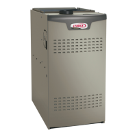
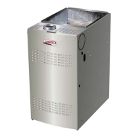
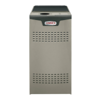
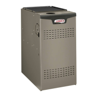
Lennox SL280UHNV Series

Lennox SL280UHNV Series
50 pages
To Next Page IconTo Next Page
Loading...
Page 1
UNIT INFORMATION
UNIT INFORMATION
Service Literature
©2017 Lennox Industries, Inc.
WARNING
Improper installation, adjustment, alteration, service
or maintenance can cause property damage, personal
injury or loss of life. Installation and service must be
performed by a licensed professional HVAC installer or
equivalent, service agency, or the gas supplier.
CAUTION
As with any mechanical equipment, contact with sharp
sheet metal edges can result in personal injury. Take
care while handling this equipment and wear gloves and
protective clothing.
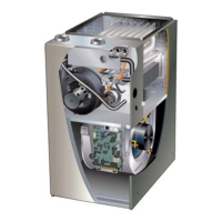
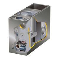
SL280UHNVseries units are 80% ef ciency gas furnac-
es used for up ow or horizontal applications only, man-
ufactured with Lennox Duralok heat exchangers formed
of aluminized steel. SL280UHNV units are available in
heating capacities of 40,000 to 100,000 Btuh and cooling
applications up to 5 tons. Refer to Engineering Handbook
for proper sizing.
Units are approved for installations up 4500 ft and facto-
ry equipped for use with natural gas only. SL280UHNV
model units are equipped with the iComfort® enabled
SureLight® two-stage variable speed integrated control.
SL280UHNV unit meets the California Nitrogen Oxides
(NOx) Standards and California Seasonal Ef ciency re-
quirements. All units use a redundant gas valve to assure
safety shut-off as required by C.S.A.
All speci cations in this manual are subject to change.
Procedures outlined in this manual are presented as a
recommendation only and do not supersede or replace lo-
cal or state codes. In the absence of local or state codes,
the guidelines and procedures outlined in this manual (ex-
cept where noted) are recommendations only and do not
constitute code.
SL280UHNV
Corp 1601-L8
ICOMFORT
®
-ENABLED SL280UHNV SERIES UNITS
Contents
I-Unit Components..........................................................4
Blower Data ..................................................................16
II-Placement and Installation ........................................31
III-Start-Up .................................................................... 31
IV-Heating System Service Checks ..............................32
V-Typical Operating Characteristics .............................34
VI-Maintenance ............................................................35
VII- Wiring and Sequence of Operation ........................38
VIII- Field Wiring With Conventional Thermostat ..........42
IX- Program Unit Capacity Size Modes ........................46
X- Troubleshooting .......................................................47

Other manuals for Lennox SL280UHNV Series

Question and Answer IconNeed help?

Do you have a question about the Lennox SL280UHNV Series and is the answer not in the manual?

Lennox SL280UHNV Series Specifications

General IconGeneral
ModelSL280UHNV Series
TypeGas Furnace
Efficiency RatingUp to 80% AFUE
Blower TypeVariable Speed
Fuel TypeNatural Gas or Propane
StagesTwo-Stage
Heating Capacity44, 000-132, 000 BTU/h
Cabinet TypeFully insulated

Summary

I-Unit Components

Control Box

Details the control box, its components, and their functions for furnace operation.

Electrostatic Discharge (ESD) Precautions

Outlines essential precautions to prevent damage to electronic components from electrostatic discharge.

Integrated Control Configuration Guide

Diagnostic LED and Push Button

Explains the function of the diagnostic LED and push button for monitoring and troubleshooting furnace status.

Diagnostic Modes

Describes various diagnostic modes like Error Code Recall, Flame Signal, and Unit Capacity/Size selection.

Soft Disable

Provides steps to address issues when the thermostat does not recognize a connected device, leading to soft disable.

DIP Switch Settings

Heating Operation DIP Switch Settings

Details DIP switch settings for thermostat selection and heating blower-off delay adjustments.

Indoor Blower Operation DIP Switch Settings

Explains DIP switch settings for adjusting indoor blower speed during cooling mode operation.

Indoor Blower Motor

Troubleshooting Motor Operation

Provides steps to diagnose and resolve issues related to the indoor blower motor's performance.

Troubleshooting Motor Windings

Details tests to check motor windings for resistance and continuity to identify faults.

Heating Components

Ignitor

Explains the SureLight® ignitor's function, voltage requirements, and how to check its resistance.

Flame Sensor

Describes the flame sensor's role in detecting flame and how to check its signal strength.

Gas Valve

Covers the redundant gas valve, its connections, and safety shut-off functions.

Thermal Switch

Explains the thermal switch's role in shutting down the unit if excessive temperatures are detected.

Burner and Orifice

Details burner settings, orifice matching, and replacement procedures.

Primary Limit Control (S10)

Describes the primary limit switch's function in preventing overheating and its automatic reset behavior.

Placement and Installation

Start-Up

Preliminary and Seasonal Checks

Lists essential checks for wiring, voltage, and connections before starting the unit.

Heating Start-Up

Provides step-by-step instructions for safely initiating the furnace's heating operation.

Heating System Service Checks

Gas Piping

Covers CAUTION and WARNINGs regarding gas piping installation, torque, and material.

Testing Gas Piping

Emphasizes leak detection methods and precautions, advising against open flames.

Manifold Pressure Measurement

Details the procedure for accurately measuring manifold pressure for correct gas flow.

Proper Combustion

Outlines acceptable CO levels for natural gas combustion and firing rate monitoring.

Proper Gas Flow (Approximate)

Explains how to check gas flow rate using a gas meter clocking method.

Typical Operating Characteristics

Blower Operation and Adjustment

Describes blower operation based on thermostat settings and how to adjust blower speed.

Temperature Rise

Explains that temperature rise depends on input, blower speed, horsepower, and static pressure.

External Static Pressure

Details the procedure for measuring external static pressure in heating and cooling modes.

Maintenance

Annual Furnace Maintenance

Lists checks for wiring, motor, gas connections, filters, burners, and heat exchanger.

Heat Exchanger and Burners Cleaning

Provides detailed steps for cleaning the heat exchanger and burners, including steam cleaning.

Wiring and Sequence of Operation

Wiring Diagrams

Shows wiring diagrams for various configurations and optional accessories.

Applications Using a Two-Stage Thermostat

Describes the heating sequence of operation when using a two-stage thermostat.

Applications Using A Single-Stage Thermostat

Details the heating sequence of operation when using a single-stage thermostat.

Field Wiring With Conventional Thermostat

DIP Switch Settings and On-Board Links

Explains how DIP switches and on-board links are used to configure wiring for various thermostat applications.

Program Unit Capacity Size Modes

Troubleshooting

Heating Sequence of Operation

Illustrates the step-by-step process of the furnace's heating sequence and potential issues.

Cooling Sequence of Operation

Details the sequence of operations for the furnace during cooling mode.

Continuous Fan Sequence of Operation

Outlines the sequence of operation for when the fan is set to run continuously.

Related product manuals