Page 32
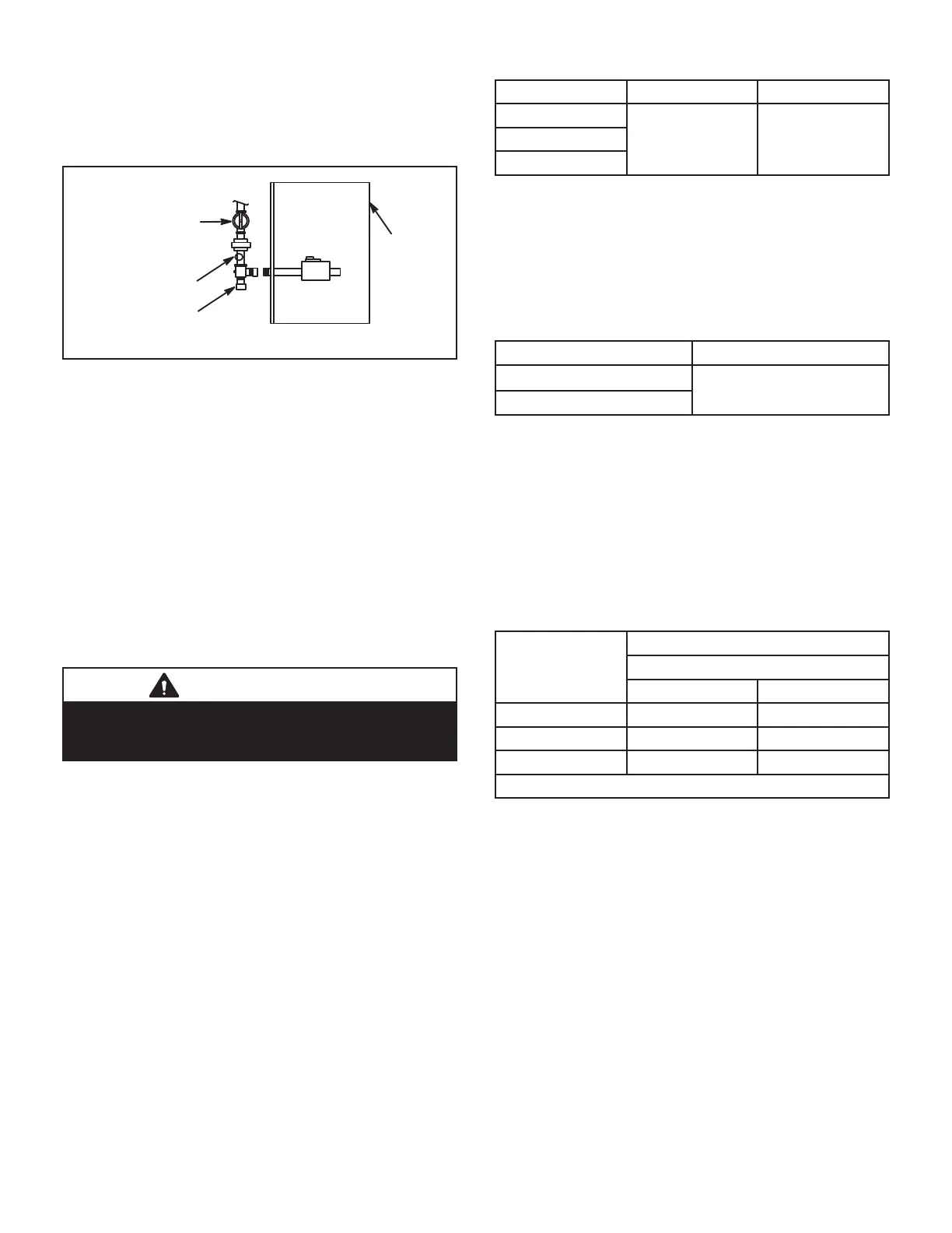
When pressure testing gas lines, the gas valve must be
disconnected and isolated. Gas valves can be damaged if
subjected to more than 0.5 psig (14” W.C.). See Figure 17.
If the pressure is greater than 0.5psig (14”W.C.), use the
manual shut-off valve before pressure testing to isolate
furnace from gas supply.
MANUAL MAIN
SHUT-OFF VALVE
WILL NOT HOLD
NORMAL TEST
PRESSURE
CAP
ISOLATE
GAS VALVE
FURNAC
1/8 NPT PLUG
FIGURE 17
When checking piping connections for gas leaks, use
preferred means. Kitchen detergents can cause harmful
corrosion on various metals used in gas piping. Use of a
specialty Gas Leak Detector is strongly recommended. It
is available through Lennox under part number 31B2001.
See Corp. 8411-L10, for further details.
Do not use matches, candles, fl ame or any other
source of ignition to check for gas leaks.
D-Testing Gas Supply Pressure
A port on the inlet side of the gas valve provides access to
the supply pressure tap. See fi gure 16. Loosen the screw
and connect a manometer to measure supply pressure.
The minimum supply line is 4.5” w.c. And the maximum
supply line is 13.0” w.c. Tighten screw after measure-
ments have been taken.
IMPORTANT
For safety, connect a shut-off valve between the
manometer and the gas tap to permit shut off of gas
pressure to the manometer.
E-Rate Check
Manifold Pressure Measurement
To correctly measure manifold pressure, follow the steps
below:
1 - Remove the threaded plug from the outlet side of
the gas valve and install a fi eld-provided barbed
fi tting. Connect measuring device “+” connection to
barbed fi tting to measure manifold pressure.
2 - Start unit on low heat and allow 15 minutes for unit
to reach steady state.
3 - After allowing unit to stabilize for 15 minutes, record
manifold pressure and compare to value given in
Table 17
4 - Repeat on high heat.
5 - Shut unit off and remove manometer as soon as
an accurate reading has been obtained. Take care
to remove barbed fi tting and replace threaded plug.
6 - Start unit and perform leak check. Seal leaks if
found.
TABLE 17
Unit High Fire Low Fire
060
3.2 - 3.6 in wc 1.3 - 1.7 in wc080
100
F- Proper Combustion
Furnace should operate minimum 15 minutes with correct
gas fl ow rate before checking combustion. Take combus-
tion sample beyond the fl ue outlet. Table 18 shows ac-
ceptable combustion for ALL SL280UHNV models. The
maximum carbon monoxide reading should not exceed
100 ppm.
TABLE 18
Firing Rate CO
2
% For Natural
High Fire
6.0 - 7.5
Low Fire
G- Proper Gas Flow (Approximate)
Furnace should operate at least 5 minutes before check-
ing gas fl ow. Determine time in seconds for two revolu-
tions of gas through the meter. (Two revolutions assures a
more accurate time.) Divide by two and compare to time
in Table 19 below.
NOTE- To obtain accurate reading, shut off all other gas
appliances connected to meter.
TABLE 19
GAS METER CLOCKING CHART
SL280N Unit
Seconds for One Revolution
Natural
1 cu ft Dial 2 cu ft Dial
060 60 120
080 45 90
100 36 72
Natural-1000 btu/cu ft

 Loading...


