Page 14
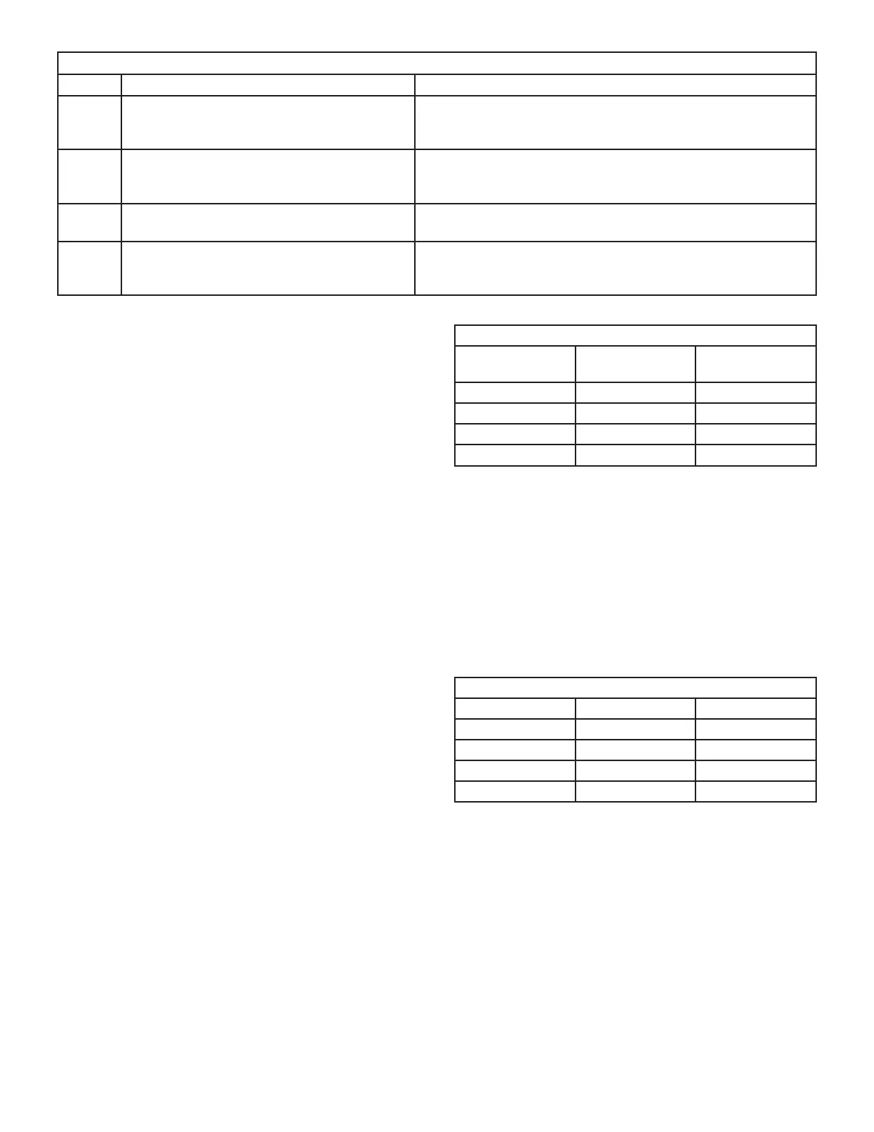
TABLE 5 Continued
Code Diagnostic Codes/Status of Equipment Action Required to Clear and Recover
E406 LSOM - Compressor open start circuit. Required amount of current is not passing through Start cur-
rent transformer. Clears the error after current is sensed in
START sensor, or after power reset.
E407 LSOM - Compressor open run circuit. Required amount of current is not passing through Run current
transformer. Clears the error after current is sensed in RUN
sensor, or 1 normal compressor run cycle, or after power reset.
E408 LSOM - Compressor contactor is welded. Compressor runs continuously. Clears the error after 1 normal
compressor run cycle or after power reset.
E409 LSOM - Compressor low voltage. Secondary voltage is below 18VAC. After 10 minutes, oper-
ation is discontinued. Clears the code after voltage is higher
than 20 VAC for 2 seconds or after power reset.
DIP Switch Settings
NOTE - All icomfort settings are set at the icomfort Wi-Fi
®
thermostat. See icomfort installation instruction. In icom-
fort communication system all DIP switch and clippable
link settings are ignored. For conventional thermostats
proceed with DIP switch and clippable link settings as out-
lined in the following.
Heating Operation DIP Switch Settings
Switch 1 -- Thermostat Selection -- This unit may be
used with either a single-stage or two-stage thermostat.
The thermostat selection is made using a DIP switch
which must be properly positioned for the particular appli-
cation. The DIP switch is factory-positioned for use with a
twostage thermostat. If a single-stage thermostat is to be
used, the DIP switch must be repositioned.
a. Select “OFF” for two-stage heating operation controlled by a
two-stage heating thermostat (factory setting);
b. Select “ON” for two-stage heating operation controlled by
a single-stage heating thermostat. This setting provides a
timed delay before second-stage heat is initiated.
Switch 2 -- Second Stage Delay (Used with Single-
Stage Thermostat Only) -- This switch is used to deter-
mine the second stage on delay when a single-stage ther-
mostat is being used. The switch is factory-set in the OFF
position, which provides a 7-minute delay before second-
stage heat is initiated. If the switch is toggled to the ON
position, it will provide a 12-minute delay before second-
stage heat is initiated. This switch is only activated when
the thermostat selector jumper is positioned for SINGLE-
stage thermostat use.
Switches 3 and 4 -- Blower-Off Delay -- The blower-on
delay of 30 seconds is not adjustable. The blower-off de-
lay (time that the blower operates after the heating de-
mand has been satisfi ed) can be adjusted by moving
switches 3 and 4 on the integrated control. The unit is
shipped from the factory with a blower-off delay of 90 sec-
onds. The blower off delay affects comfort and is adjust-
able to atisfy individual applicationsAdjust the blower off
delay to achieve a supply air temperature between 90°
and 110°F at the exact moment that the blower is de-en-
ergized. Longer off delay settings provide lower supply air
temperatures; shorter settings provide higher supply air
temperatures. Table 6 provides the blower off timings that
will result from different switch settings.
TABLE 6
Blower Off Delay Switch Settings
Blower Off Delay
Seconds
Switch 3 Switch 4
60 On Off
90 (factory) Off Off
120 Off On
180 On On
Indoor Blower Operation DIP Switch Settings
Switches 5 and 6 -- Cooling Mode Blower Speed -- The
unit is shipped from the factory with the dip switches po-
sitioned for high speed (4) indoor blower motor operation
during the cooling mode. Table 7 provides the cooling
mode blower speeds that will result from different switch
settings. Switches 5 and 6 set the blower cfm for second-
stage cool. The integrated control automatically ramps
down to 70% of the second-stage cfm for fi rst-stage cfm.
Refer to tables for corresponding cfm values.
TABLE 7
Cooling Mode Blower Speeds
Speed Switch 5 Switch 6
Low On On
Medium Low Off On
Medium High On Off
High (factory) Off Off
. Switches 7 and 8 -- Cooling Blower Speed Adjust-
ment
-- The unit is shipped from the factory with the dip switches
positioned for NORMAL (no) adjustment. The dip switches
may be positioned to adjust the blower speed by +10% or
-10% to better suit the application. Table 8 below provides
blower speed adjustments that will result from different
switch settings. Refer to tables for corresponding cfm val-
ues.

 Loading...


