Page 27
C- Heating Components
1. Ignitor
The SureLight® ignitor is made of durable silicon nitride.
Ignitor longevity is enhanced by controlling voltage to the
ignitor. The integrated control provides a regulated 120
volts to the ignitor for a consistent ignition and long ignitor
life. Ohm value should be 39 to 70. See Figure 13 for ignit-
or location and Figure 14 for ignitor check out.
NOTE - The SL280UHNV furnace contains electronic
components that are polarity sensitive. Make sure that the
furnace is wired correctly and is properly grounded.
2. Flame Sensor
A fl ame sensor is located on the top of the air gas ple-
num. See Figure 13. The sensor can be removed for ser-
vice without removing the the burner. During operation,
fl ame is sensed by current passed through the fl ame and
sensing electrode. The SureLight control allows the gas
valve to remain open as long as fl ame signal is sensed.
To check fl ame sense signal use the push-button found
on the integrated control and go to Field Test Mode. The
menu will display the fl ame signal. See Table 15 for fl ame
signal.
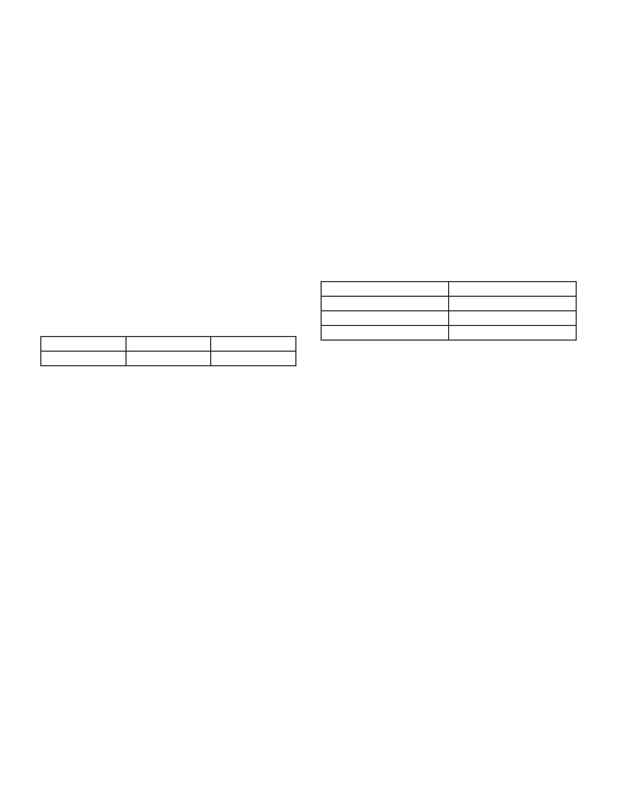
TABLE 15
Flame Signal in Microamps
Normal Low Drop Out
2.6 or greater 2.5 or less 1.1
3. Gas Valve
The valve (Figure 16) is internally redundant to assure
safety shut-off. If the gas valve must be replaced, the
same type valve must be used.
24VAC terminals and gas control knob are located on the
valve. A wire harness connects the terminals from the gas
valve to the electronic ignition control. 24V applied to the
terminals energizes the valve. Inlet and outlet pressure
taps are located on the valve. A regulator adjustment
screw is located on the valve.
4. Thermal Switch
The auto-reset switch is located on the front of the intake
air elbow. The switch will safely shut the unit down if ex-
cessive temperatures are detected. See Figure 13. When
the switch senses excessive temperature, the circuit
breaks and the ignition control immediately stops ignition
and closes the gas valve.
5. Burner and Orifi ce
Burners are factory set and require no adjustment. Always
operate the unit with air gas plenum in place. The burn-
er has one orifi ce located between the gas valve and the
air intake assembly (Figure 13). To check or replace the
orifi ce remove the intake air screen, coupling and intake
air elbow.Using a 5/8” socket, go through the elbow and
unscrew the gas orifi ce. The burner uses an orifi ce (see
Table 16) that is precisely matched to the burner input.
The burner can be removed for service. If burner has been
removed, it is critical to replace all gaskets.
TABLE 16
Gas Orifi ces
Unit Input Orifi ce Size (0 - 4500 ft)
060 0.0595
080 0.0689
100 0.0810
6. Primary Limit Control (S10)
The primary limit (S10) is located in the heating vestibule
panel. When excess heat is sensed in the heat exchanger,
the limit will open. If the limit is open, the furnace control
energizes the supply air blower and closes the gas valve.
The limit automatically resets when unit temperature re-
turns to normal. The switch must reset within three min-
utes or the SureLight control will go into Watch guard for
one hour. The switch is factory set and cannot be adjust-
ed. The switch may have a different set point for each unit
model number. See Lennox Repair Parts Handbook if limit
switch must be replaced.

 Loading...


