Page 8
TABLE 1
NON-COMBUSTIBLE FLOOR OPENINGSIZE
Cabinet Width
Front to Rear Side to Side
in mm in mm
B Cabinet 17 - 1/2” 19 - 3/4 502 16 - 5/8 422
C Cabinet 21” 19 - 3/4 502 20 - 1/8 511
NOTE - Floor opening dimensions listed are 1/4 inch (6 mm) larger than
the unit opening. See dimension drawing on page 2.
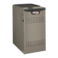
SUPPLY AIR
PLENUM
PROPERLY
SIZED FLOOR
OPENING
FURNACE
FIGURE 8
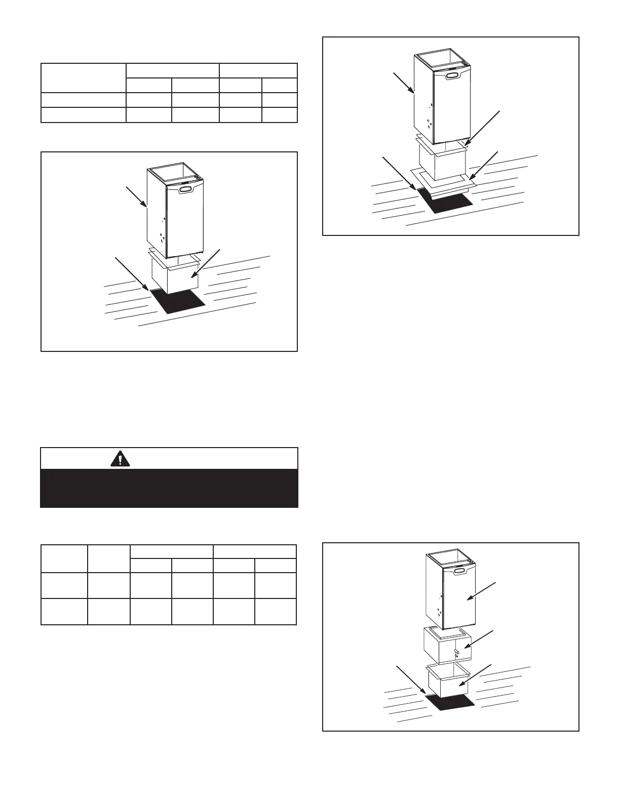
Installation on Combustible Flooring (FIGURE 9)
1 - When unit is installed on a combustible oor,
a downow combustible ooring base must be
installed between the furnace and the oor. The
base must be ordered separately. See TABLE 2 for
opening size to cut in oor.
CAUTION
The furnace and combustible ooring base shall not be
installed directly on carpeting, tile, or other combustible
material other than wood ooring.
TABLE 2
COMBUSTIBLE FLOORING BASE OPENING SIZE
Cabinet
Width
Catalog
Number
Front to Rear Side to Side
in mm in mm
B Cabinet
17 - 1/2”
11M60 22 559 18 - 3/4 476
C Cabinet
21”
11M61 22 559 22 - 3/4 578
FURNACE
SUPPLY AIR
PLENUM
COMBUSTIBLE
FLOORING BASE
PROPERLY
SIZED FLOOR
OPENING
FIGURE 9
2 - After opening is cut, set combustible ooring base
into opening.
3 - Check berglass strips on combustible ooring
base to make sure they are properly glued and
positioned.
4 - Lower supply air plenum into combustible ooring
base until plenum anges seal against berglass
strips.
NOTE - Be careful not to damage berglass strips.
Check for a tight seal.
5 - Set the furnace over the plenum.
6 - Ensure that the seal between the furnace and
plenum is adequate.
Installation on Cooling Coil Cabinet (FIGURE 10)
NOTE - Downow combustible ooring base is not used.
1 - Refer to reverse-ow coil installation instructions for
correctly sized opening in oor and installation of
cabinet.
2 - When cooling cabinet is in place, set and secure
the furnace according to the instructions that are
provided with the cooling coil. Secure the furnace
to the cabinet.
3 - Seal the cabinet and check for air leaks.
COOLING COIL
PLENUM
PROPERLY
SIZED FLOOR
OPENING
FURNACE
FIGURE 10

 Loading...