Page 52
Manifold Pressure Measurement (FIGURE 52)
To correctly measure manifold pressure, the dierential
pressure between the positive gas manifold and the neg-
ative burner box must be considered. Use pressure test
adapter kit (available as Lennox part 10L34) to assist in
measurement.
1 - Remove the threaded plug from the outlet side of
the gas valve and install a eld-provided barbed
tting. Connect measuring device “+” connection to
barbed tting to measure manifold pressure.
2 - Tee into the gas valve regulator vent hose and
connect measuring device “-” connection.
3 - Start unit on low heat (35% rate) and allow 5 minutes
for unit to reach steady state.
4 - While waiting for the unit to stabilize, notice the
ame. Flame should be stable and should not lift
from burner. Natural gas should burn blue.
5 - After allowing unit to stabilize for 5 minutes, record
manifold pressure and compare to value given in
TABLE 32.
6 - Repeat steps 3, 4 and 5 on high heat.
7 - Shut unit o and remove manometer as soon as
an accurate reading has been obtained. Take care
to remove barbed tting and replace threaded plug.
8 - Start unit and perform leak check. Seal leaks if
found.
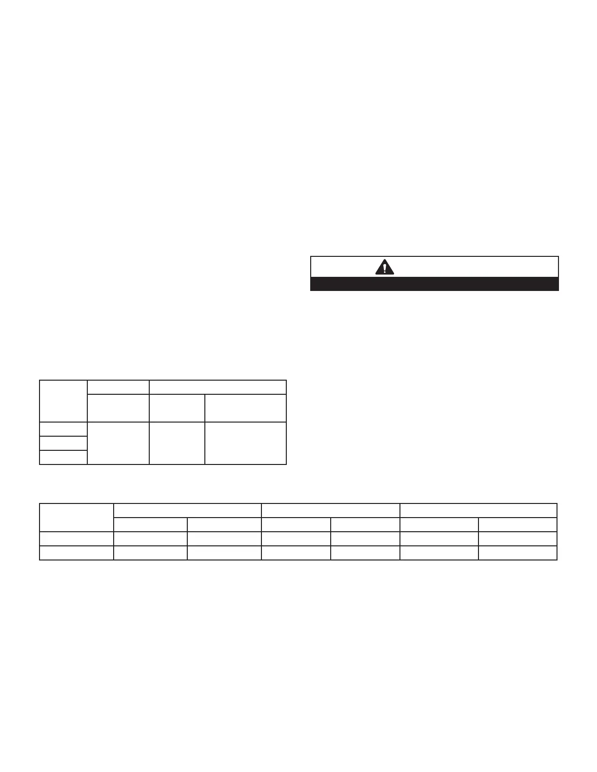
TABLE 31
Conversion Kit Requirements
Model
Input Size
LP/Propane High Altitude Pressure Switch
0 - 10,000 ft
(0 - 3048m)
0 - 7500 ft
(0 - 2286m)
7501 ft - 10,000 ft
(287 - 3048m)
070
65W77
Not
Required
14T67090
110
Operating Pressure Signal (Delta P) Measurement
(FIGURE 53)
Operating pressure signal can be taken while the manifold
pressure pressure check is taken (using two measuring
devices). Or, taken after the manifold pressure measure-
ment is complete.
1 - Tee into the negative line between the gas valve and
pressure switch and connect to measuring device
negative “-”.
2 - Tee into the positive line between the gas valve and
pressure switch and connect to measuring device
positive “+”.
3 - Start unit on low heat (35% rate) and allow 5 minutes
for unit to reach steady state.
4 - After allowing unit to stabilize for 5 minutes, record
operating pressure signal and compare to value
given in TABLE 32.
5 - Repeat steps 3 on 4 high heat.
WARNING
Do not attempt to make adjustments to the gas valve.
.
TABLE 32
Manifold and Operating Signal Pressures in inches 0 - 7500 ft (0 - 2286 m)
SLP99 Firing
Rate
Manifold Pressure Natural Gas Manifold Pressure LP/Propane Operating Pressure Signal (Delta P)
Min Max Min Max Min Max
Low 0.4 0.95 1.2 2.8 0.20 0.40
High 3.0 3.8 9.1 10.5 0.95 1.25
NOTE - A natural to LP/propane gas changeover kit is necessary to convert this unit. Refer to the changeover kit instal-
lation instruction for the conversion procedure.
NOTE - The values given in table are measurements only. The gas valve should NOT be adjusted.

 Loading...