Page 28
5 - If unit will be started immediately upon completion
of installation, prime trap per procedure outlined in
Unit Start-Up section.
Condensate line must slope downward away from the trap
to drain. If drain level is above condensate trap, conden-
sate pump must be used. Condensate drain line should
be routed within the conditioned space to avoid freezing of
condensate and blockage of drain line. If this is not possi-
ble, a heat cable kit may be used on the condensate trap
and line. Heat cable kit is available from Lennox in various
lengths; 6 ft. (1.8m) - kit no. 26K68 and 24 ft. (7.3m) - kit
no. 26K69.
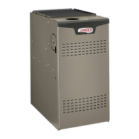
Furnace with Evaporator Coil
Using a Separate Drain
Drain
Field Provided Vent
1” min. 2” max. above
condensate drain.
Condensate
Drain Connection
Evaporator Drain Line
(vent required)
FIGURE 40
IMPORTANT
When combining the furnace and evaporator coil
drains together, the A/C condensate drain outlet
must be vented to relieve pressure in order for the
furnace pressure switch to operate properly.
Coil Using a Common Drain
Field Provided Vent
1” min. 2” max. above
condensate drain.
Evaporator Drain Line
(vent required)
Condensate
Drain Connection
FIGURE 41
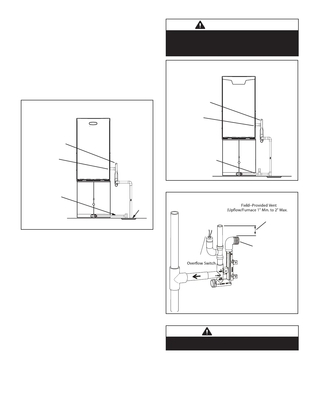
HorizontalFurnace4” Min.to5” Max.above
condensatedrain connection)
FurnaceCondensate
Drain
Connection
From Evaporator Coil
Optional
Condensate Trap With Optional Overflow Switch
FIGURE 42
CAUTION
Do not use copper tubing or existing copper
condensate lines for drain line.

 Loading...