Page 27
Condensate Piping
This unit is designed for either right- or left-side exit of
condensate piping. Refer to FIGURE 37 and FIGURE 38
for condensate trap locations.
NOTE - If necessary the condensate trap may be installed
up to 5’ away from the furnace. Use PVC pipe to connect
trap to furnace condensate outlet. Piping from furnace
must slope down a minimum of 1/4” per ft. toward trap.
1 - Determine which side condensate piping will exit
the unit, location of trap, eld-provided ttings and
length of PVC pipe required to reach available drain.
2 - Use a large at head screw driver or a 1/2” drive
socket extension and remove plug (FIGURE 37)
from the cold end header box at the appropriate
location on the side of the unit. Install provided 3/4
NPT street elbow tting into cold end header box.
Use Teon tape or appropriate pipe dope
NOTE - Cold end header box drain plugs are factory in-
stalled. Check the unused plug for tightness to prevent
leakage.
CONDENSATE TRAP AND PLUG LOCATIONS
Trap
(same on
right side)
Plug
(same on left
side)
1-1/2 in.
FIGURE 37
Install the cap over the clean out opening at the base of
the trap. Secure with clamp. See FIGURE 43.
3 - Install drain trap using appropriate PVC ttings, glue
all joints. Glue the provided drain trap as shown in
FIGURE 43. Route the condensate line to an open
drain.
4 - FIGURE 40 shows the furnace and evaporator coil
using a separate drain. If necessary, the condensate
line from the furnace and evaporator coil can
drain together. See FIGURE 41 and FIGURE 42.
The eld provided vent must be a minimum 1” to
a maximum 2” length above the condensate drain
outlet connection.
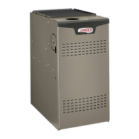
CONDENSATE TRAP LOCATION
(shown with right side exit of condensation)
5’ max.
to drain
1” min.
2” max.
Trap can be installed a maximum
of 5ft. from furnace (*PVC only)
Field Provided Vent
1” min. 2” max. above
condensate drain.
*Piping from furnace must slope down a
minimum 1/4” per ft. toward trap
FIGURE 38
NOTE - If necessary the condensate trap may be installed
up to 5 feet away from the furnace. Piping from furnace
must slope down a minimum of 1/4” per ft. toward trap.
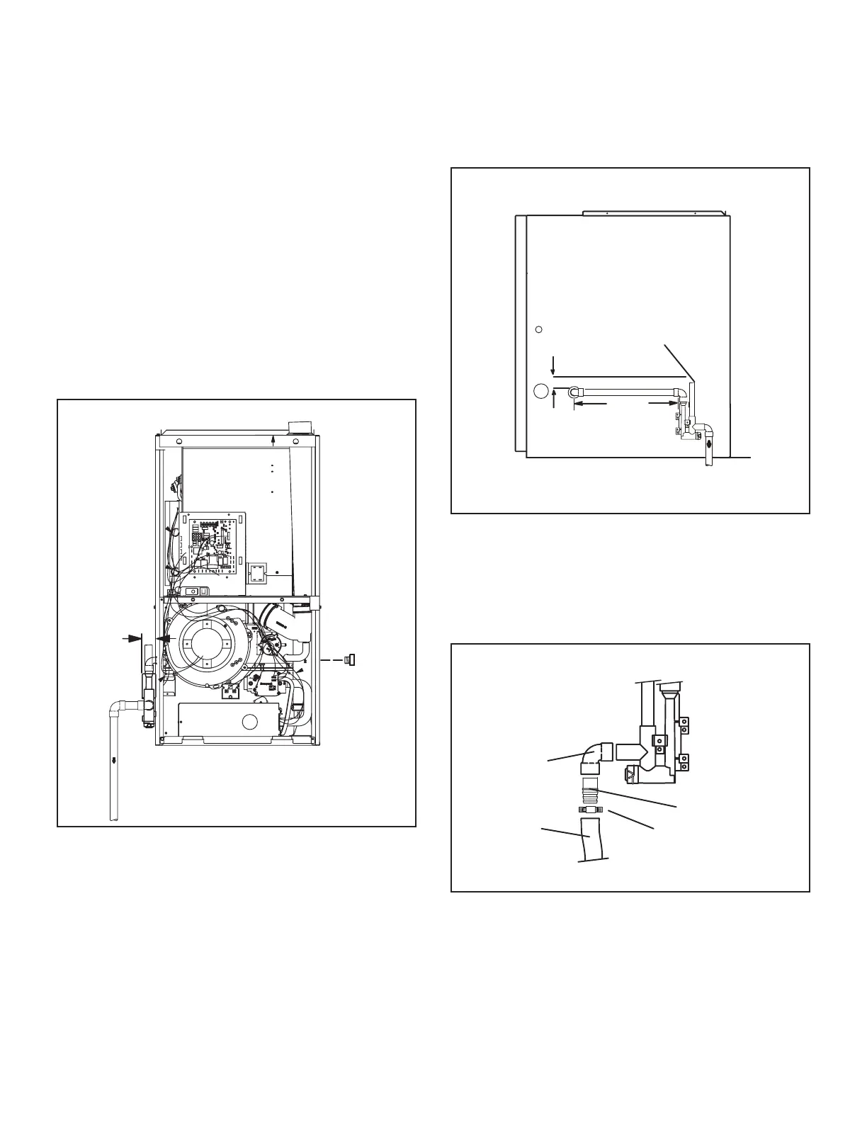
NOTE - Appropriately sized tubing and barbed tting may
be used for condensate drain. Attach to the drain on the
trap using a hose clamp. See FIGURE 39.
Field Provided Drain Components
Tubing
Hose Clamp
Barbed Fitting
Elbow
FIGURE 39

 Loading...