Page 7
3 - Clock gas meter to ensure that the unit is operating
at the specied ring rate for each stage of operation.
Check supply, manifold and signal pressures at
35, 70 and 100% capacity as outlined in the unit
Service Literature. If manifold pressure adjustment
is necessary, consult the Service Literature for unit
specic information on adjusting gas pressure.
Not all gas valves are adjustable. Verify correct
temperature rise
CAUTION
As with any mechanical equipment, contact with
sharp sheet metal edges can result in personal
injury. Take care while handling this equipment and
wear gloves and protective clothing.
Perform a general system test. Turn on the furnace to
check operating functions such as the start-up and shut-
o operation.
1 - Check the operation of the ignition system, inspect
and clean ame sensor. Check microamps before
and after. Check controls and safety devices (gas
valve, ame sensor, temperature limits). Consult
Service Manual for proper operating range. Thermal
Limits should be checked by restricting airow and
not disconnecting the indoor blower. For additional
details, please see Service and Application Note
H049.
2 - Verify that system total static pressure and airow
settings are within specic operating parameters.
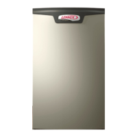
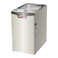
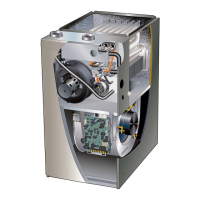
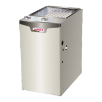
The following repair parts are available through Lennox dealers. When ordering parts, include the complete furnace
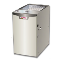
model number listed on the CSA International nameplate -- Example: SLP99DF070V36B. All service must be done by
a licensed professional installer (or equivalent), a service agency, or the gas supplier.
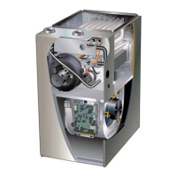
RepairParts List
Cabinet Parts
Outer access panel
Blower access panel
Top cap
Control Panel Parts
Transformer
SureLight® integrated control
Door interlock switch
Circuit breaker
Blower Parts
Blower wheel
Motor
Blower housing cut-o plate
Heating Parts
Flame Sensor
Heat exchanger assembly
Gas manifold
Combustion air inducer
Gas valve
Main burner cluster
Main burner orices
Pressure switches
Ignitor
Primary limit control
Flame rollout switches
 Loading...
