Page 69
VI-TYPICAL OPERATING CHARACTERISTICS
A-Blower Operation and Adjustment
1 - Blower operation is dependent on thermostat control
system.
2 - Generally, blower operation is set at thermostat subbase
fan switch. With fan switch in ON position, blower oper
ates continuously. With fan switch in AUTO position,
blower cycles with demand or runs continuously while
heating or cooling circuit cycles.
3 - Depending on the type of indoor thermostat, blower and
entire unit will be off when the system switch is in OFF
position.
B-Temperature Rise
Temperature rise for SLP99UHV units depends on unit in
put, blower speed, blower horsepower and static pressure
as marked on the unit rating plate. The blower speed must
be set for unit operation within the range of “TEMP. RISE
°F” listed on the unit rating plate.
To Measure Temperature Rise:
1 - Place plenum thermometers in the supply and return air
plenums. Locate supply air thermometer in the first hori
zontal run of the plenum where it will not pick up radiant
heat from the heat exchanger.
2 - Set thermostat for heat call. Unit must operate on sec
ond-stage heat. If using a single-stage thermostat fur
nace must fire at least 10 minutes before switching to
second-stage heat.
3 - After plenum thermometers have reached their highest
and steadiest readings, subtract the two readings. The
difference should be in the range listed on the unit rating
plate. If the temperature is too low, decrease blower
speed. If temperature is too high, first check the firing
rate. Provided the firing rate is acceptable, increase
blower speed to reduce temperature.
C-External Static Pressure
1 - Tap locations shown in figure 54.
2 - Punch a 1/4” diameter hole in
supply and return air ple
nums. Insert manometer
hose flush with inside edge of
hole or insulation. Seal
around the hose with perma
gum. Connect the zero end of
the manometer to the dis
charge (supply) side of the system. On ducted systems,
connect the other end of manometer to the return duct
as above.
3 - With only the blower motor running and the evaporator
coil dry, observe the manometer reading. Adjust blower
motor speed to deliver the air desired according to the
job requirements.
4 - External static pressure drop must not be more than
0.8” W.C. in the heating mode and must not exceed 1.0”
W.C in the cooling mode.
5 - Seal the hole when the check is complete.
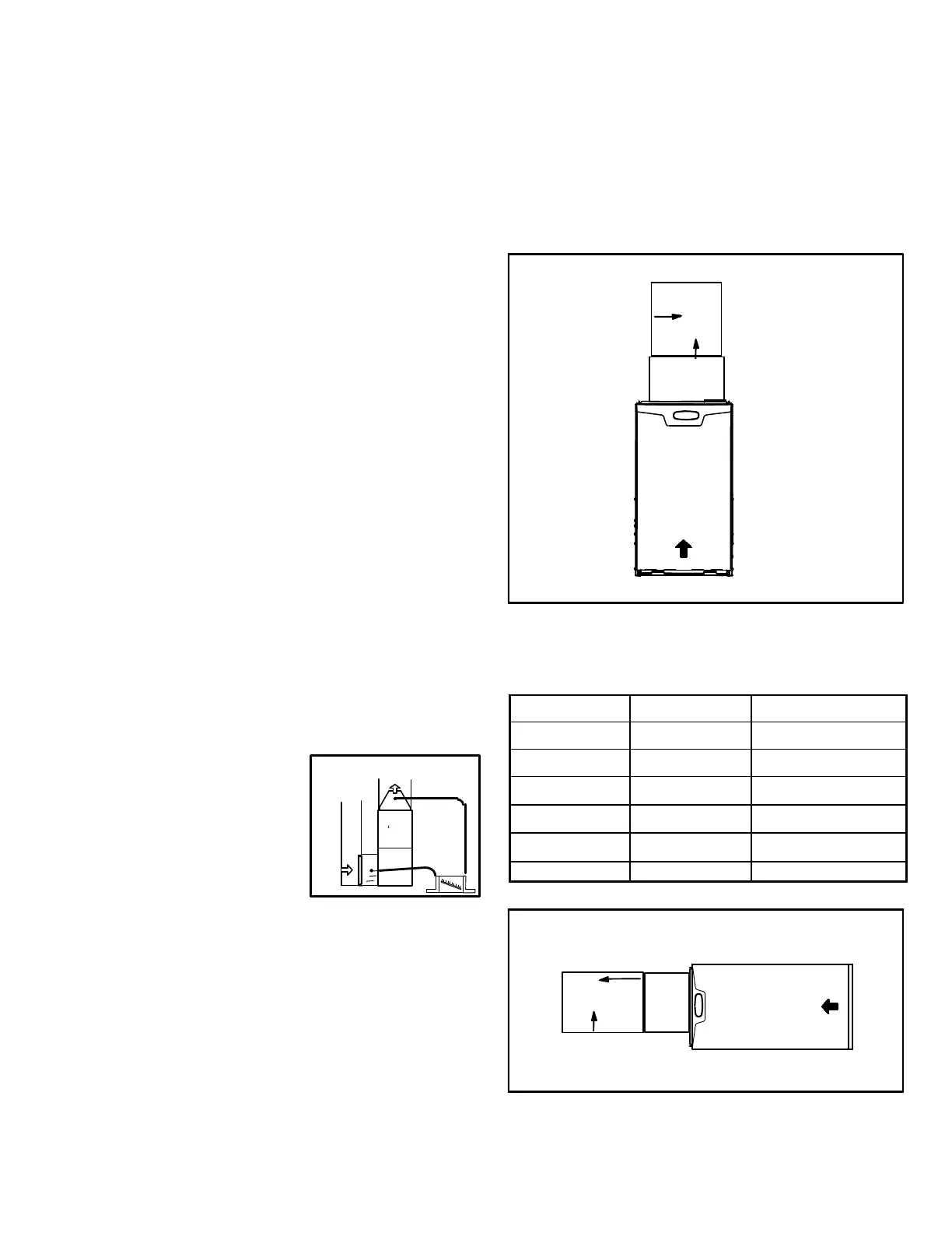
D-Discharge Air Temperature Sensor
Units may have a discharge air temperature sensor located
in the supply duct. If the sensor is suspect, check the loca
tion using Figures 55, 56 and 57 and tables 34, 35 and 36.
Figure 58 shows field wiring to the furnace control. If the lo
cation and wiring are correct but the sensor is not working
properly replace the sensor.
FIGURE 55
Coil
Plenum
a
b
Upflow
AIR FLOWAIR FLOW
Discharge Air Temperature Sensor Location
TABLE 34
Upflow
“a” “b”
070V36B 6” center
090V36C 12” center
090V48C 1” 2” from left
090V60C 3” 2-1/2” from left
110V60C 3” 2” from left
135V60D 1” 4” from left
FIGURE 56
Discharge Air Temperature Sensor Location
a
b
Coil
Plenum
Horizontal Left
AIR FLOW
Horizontal Left
FIGURE 54
STATIC PRESSURE TEST
+
-

 Loading...


