Page 64
8 - Move gas valve switch to the ON position. See
FIGURE 48. Do not force.
9 - Replace the upper access panel.
10 - Turn on all electrical power to to the unit.
11 - Set the thermostat to desired setting.
NOTE - When unit is initially started, steps 1 through
11 may need to be repeated to purge air from gas
line.
12 - If the appliance will not operate, follow the
instructions “Turning O Gas to Unit” and call your
service technician or gas supplier.
Turning O Gas to Unit
1 - Set the thermostat to the lowest setting.
2 - Turn o all electrical power to the unit if service is to
be performed.
3 - Remove the upper access panel.
4 - Move the gas valve switch to the OFF position.
5 - Replace the upper access panel.
Failure To Operate
If the unit fails to operate, check the following:
1 - Is the thermostat calling for heat?
2 - Are access panels securely in place?
3 - Is the main disconnect switch closed?
4 - Is there a blown fuse?
5 - Is the lter dirty or plugged? Dirty or plugged lters
will cause the limit control to shut the unit o.
6 - Is gas turned on at the meter?
7 - Is the manual main shut-o valve open?
8 - Is the gas valve turned on?
9 - Is the unit ignition system in lock out? If the unit
locks out again, inspect the unit for blockages.
10 - Is blower harness connected to integrated control?
Furnace will not operate unless harness is
connected.
C-Safety or Emergency Shutdown
Turn o unit power. Close manual and main gas valves.
D-Extended Period Shutdown
Turn o thermostat or set to “UNOCCUPIED” mode. Close
all gas valves (both internal and external to unit) to guar-
antee no gas leak into combustion chamber. Turn o pow-
er to unit. All access panels and covers must be in place
and secured.
V-HEATING SYSTEM SERVICE CHECKS
A-CSA Certication
All units are CSA design certied without modications.
Refer to the SLP99UHV Installation Instruction.
B-Gas Piping
CAUTION
If a exible gas connector is required or allowed by the
authority that has jurisdiction, black iron pipe shall be
installed at the gas valve and extend outside the furnace
cabinet. The exible connector can then be added
between the black iron pipe and the gas supply line.
WARNING
Do not over torque (800 in-lbs) or under torque (350 in-
lbs) when attaching the gas piping to the gas valve.
Gas supply piping should not allow more than 0.5”W.C.
drop in pressure between gas meter and unit. Supply gas
pipe must not be smaller than unit gas connection.
Compounds used on gas piping threaded joints should be
resistant to action of liqueed petroleum gases.
C-Testing Gas Piping
IMPORTANT
In case emergency shutdown is required, turn o the
main shut-o valve and disconnect the main power to
unit. These controls should be properly labeled by the
installer.
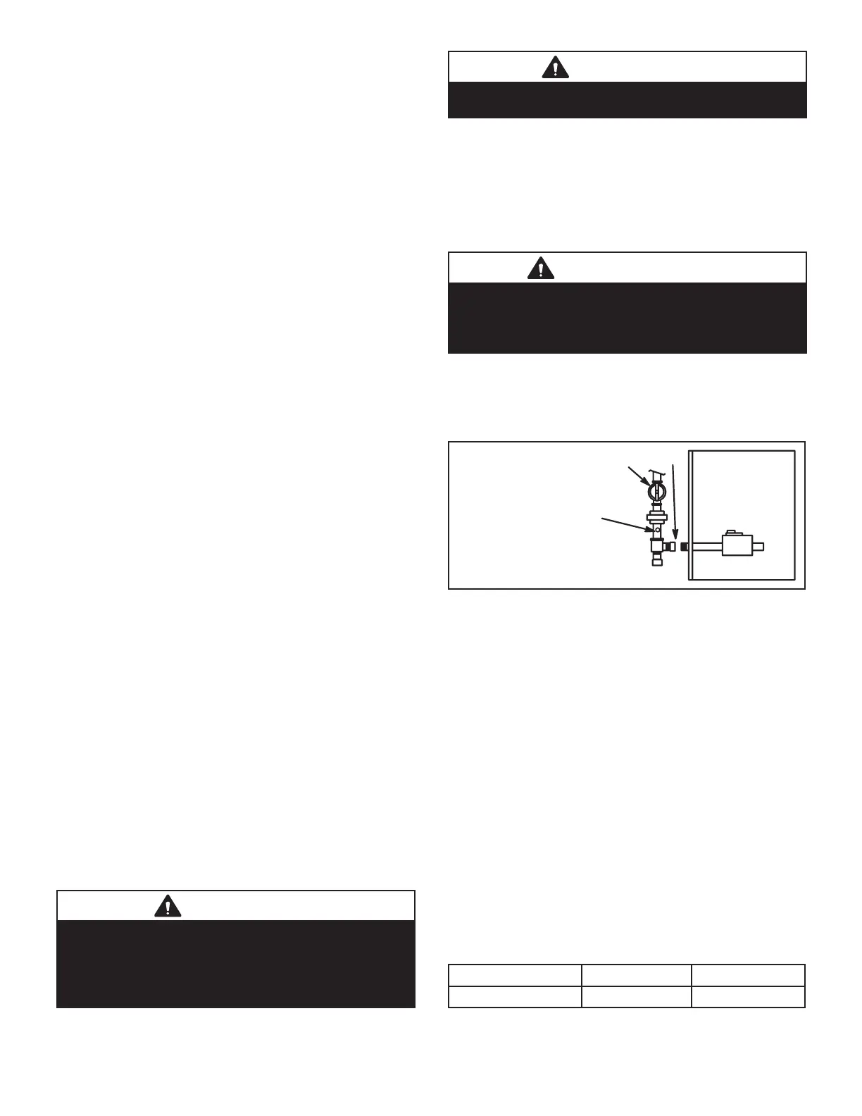
When pressure testing gas lines, the gas valve must be
disconnected and isolated. Gas valves can be damaged if
subjected to more than 0.5psig (14” W.C.). See FIGURE
49.
VALVE WILL NOT HOLD
NORMAL TEST PRESSURE
CAP
FURNACE
ISOLATE
GAS VALVE
N.P. T. PLUGGED TAP
FIGURE 49
When checking piping connections for gas leaks, use
preferred means. Kitchen detergents can cause harmful
corrosion on various metals used in gas piping. Use of a
specialty Gas Leak Detector is strongly recommended. It
is available through Lennox under part number 31B2001.
See Corp. 8411-L10, for further details.
Do not use matches, candles, ame or any other source o
ignition to check for gas leaks.
D-Testing Gas Supply Pressure
When testing supply gas pressure, connect test gauge to
supply pressure tap on the gas valve. See FIGURE 48.
Check gas line pressure with unit ring at maximum rate.
Low pressure may result in erratic operation or underre.
High pressure can result in permanent damage to gas
valve or overre. See TABLE 27 for operating pressure at
unit gas connection (line).
On multiple unit installations, each unit should be checked
separately, with and without units operating. Supply pres-
sure must fall within range listed in TABLE 27.
TABLE 27
All Units Natural LP/Propane
Line Pressure WC” 4.5 - 10.5
11.0 - 13.0

 Loading...


