Page 70
TABLE 34
Sensor Type 1 Upow
Unit “a” “b”
070V36B 6” center
090V36C 12” center
090V48C 1” 2” from left
090V60C 3” 2-1/2” from left
110V60C 3” 2” from left
135V60D 1” 4” from left
TABLE 35
Sensor Type 2 Upow
Unit “a” “b”
070V36B 2” center
090V36C 3” center
090V48C 2” 7” from right
090V60C 3” 4” from right
110V60C 2” 8” from right
135V60D 2” 7” from right
Discharge Air Temperature Sensor Location
a
b
Coil
Plenum
Horizontal Left
AIR FLOW
Horizontal Left
FIGURE 57
TABLE 36
Sensor Type 1 Horizontal Left
Unit “a” “b”
070V36B 19” center
090V36C 19” center
090V48C 3” 2” from bottom
090V60C 1” 2” from bottom
110V60C 3” 2” from bottom
135V60D 1” 5” from bottom
TABLE 37
Sensor Type 2 Horizontal Left
Unit “a” “b”
070V36B 19” center
090V36C 19” center
090V48C 3” 2” from bottom
090V60C 1” 2” from bottom
110V60C 3” 2” from bottom
135V60D 1” 5” from bottom
Discharge Air Temperature Sensor Location
Coil
Plenum
b
a
Horizontal Right
AIR FLOW
FIGURE 58
TABLE 38
Sensor Type 1 Horizontal Right
Unit “a” “b”
070V36B 15” center
090V36C 19” center
090V48C 3” 2” from top
090V60C 1” 2” from top
110V60C 3” 2” from top
135V60D 1” 5” from top
TABLE 39
Sensor Type 2 Horizontal Right
Unit “a” “b”
070V36B 5” center
090V36C 2” 8” from bottom
090V48C 3” center
090V60C 3” 7” from top
110V60C 3” center
135V60D 2” 7” from top
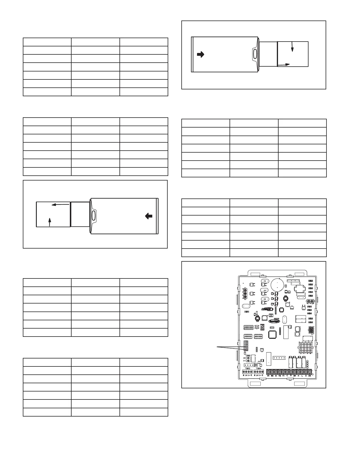
Discharge Air Temperature Sensor Wiring
+
DISCHARGE AIR
SENSOR
TERMINALS
W915
W951
W914
EAC
HUM
FIGURE 59

 Loading...


