3
Application
V8AHUK024-3P, V8AHUK048-3P and V8AHUK096-3P
AHU Control Kits enable Lennox VRF VRB heat recovery
and VPB heat pump outdoor units to operate Lennox non-
VRF indoor units and 3rd party non-communicating indoor
units (coils, air handler units and furnaces) with 1 to 20
tons capacity of each unit. 2, 3 or 4 kits are allowed in
parallel to control single large indoor equipment.
Throttling devices (TXV, orice, piston and cap tube, etc.)
in the indoor unit shall be removed, additional modications
may be needed. Only Lennox VRF wired local controller
V0STAT51P-3 is allowed with the AHU Control Kit. Two
typical application layouts are shown in Figure 1 and
Figure 2.
Designs with these kits require approval by the
Lennox VRF Applications Team prior to installation.
VRF
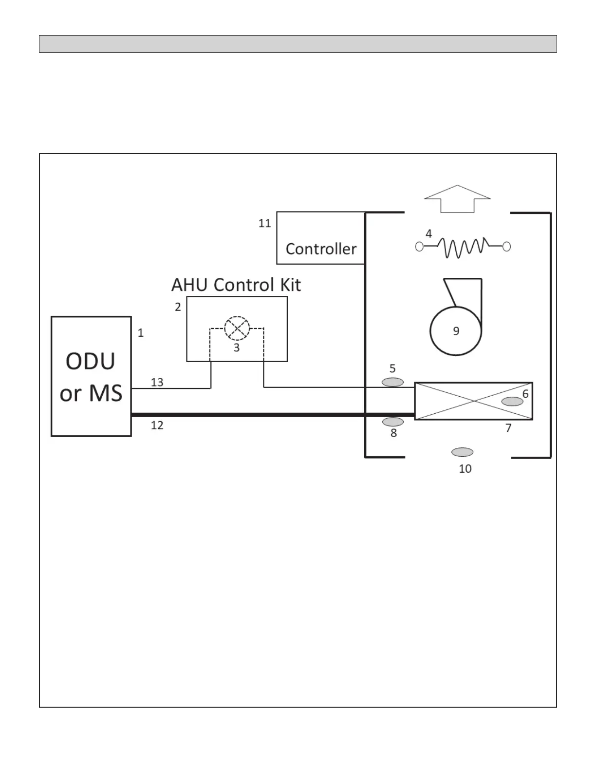
Figure 1. Electric Air Handler with Electric Auxiliary Heat & AHU Control Kit
1 - Outdoor Unit or MS Box
2 - AHU Control Kit
3 - Electronic Expansion Valve
4 - Heating Elements
5 - Entering Coil Temperature Sensor (metered side, Downstream of EXV) (T2A)
6 - Mid-Coil Temperature Sensor (T2)
7 - Coil
8 - Suction Line Temperature Sensor (T2B)
9 - Blower
10 - Return Air Temp Sensor (T1)
11 - Controller
12 - Suction Line
13 - Liquid Line
14 - Air Handler
NOTE - All AHU Control Kit Components are listed in Cooling Conguration.
 Loading...